Table of Contents
Advertisement
Quick Links
This document is provided with the DRV8889-Q1 customer evaluation module (EVM) as a supplement to
the
DRV8889-Q1 Automotive Stepper Motor Driver
installation and usage of the DRV8889-Q1EVM GUI. For additional details on hardware connections refer
to the
DRV8889-Q1EVM User's
......................................................................................................................
1
2
3
3.1
3.2
3.3
........................................................................................................................
4
1
2
Figure 2. DRV8889-Q1 EVM GUI (Device Connection pane)
3
4
5
6
7
8
9
10
11
12
Trademarks
MSP430 is a trademark of Texas Instruments.
Windows is a registered trademark of Microsoft Corporation.
All other trademarks are the property of their respective owners.
SLVUBM4A - April 2019 - Revised October 2019
Submit Documentation Feedback
DRV8889-Q1EVM GUI User's Guide
Guide.
.............................................................................................
..............................................................................................................
...........................................................................................................
..................................................................................
....................................................................................
.....................................................................................................
........................................................................................
.....................................................................................................
...............................................................................................................
...................................................................................
................................................................................
Copyright © 2019, Texas Instruments Incorporated
SLVUBM4A - April 2019 - Revised October 2019
datasheet. This document only describes the
Contents
....................................................................
List of Figures
.........................................................
.................................................................
................................................................
...................................................................
....................................................................
DRV8889-Q1EVM GUI User's Guide
User's Guide
2
2
2
2
2
2
12
3
3
4
4
5
6
7
8
9
10
11
12
1
Advertisement
Table of Contents

Subscribe to Our Youtube Channel
Related Manuals for Texas Instruments DRV8889-Q1EVM


Summary of Contents for Texas Instruments DRV8889-Q1EVM
-
Page 1: Table Of Contents
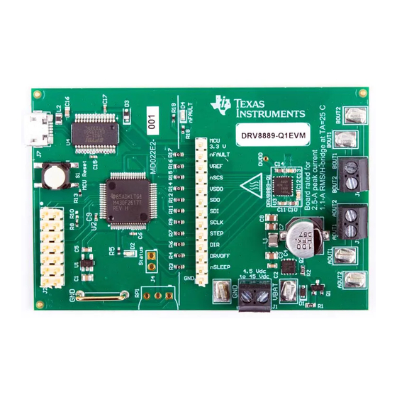
This document is provided with the DRV8889-Q1 customer evaluation module (EVM) as a supplement to DRV8889-Q1 Automotive Stepper Motor Driver datasheet. This document only describes the installation and usage of the DRV8889-Q1EVM GUI. For additional details on hardware connections refer to the DRV8889-Q1EVM User's Guide. -
Page 2: Overview
Enable the motor power supply. For additional details on hardware connections refer to the DRV8889- Q1EVM User's Guide. Click on DRV8889-Q1EVM GUI shortcut either on the desktop or from the start menu to run the GUI application. Use the DRV8889-Q1EVM GUI •... -
Page 3: Drv8889-Q1 Evm Gui (Home Page)
‘Error: no serial ports found.’ • If there are more than one DRV8889-Q1EVM boards connected, the first matching device will be connected automatically. In order to switch to another EVM, – Click Options -> Serial Port. A serial port configuration popup is displayed as shown below in Figure –... -
Page 4: Serial Port Configuration
The GUI allows the user to control the stepper motion profile in two modes – Speed Mode and Step Mode. To toggle between the modes, use the toggle button at the top of the screen. DRV8889-Q1EVM GUI User's Guide SLVUBM4A – April 2019 – Revised October 2019 Submit Documentation Feedback Copyright © 2019, Texas Instruments Incorporated... -
Page 5: Controls Available For Speed Mode
It will do this continuously until 'Stop Steps' is clicked. Figure 6 shows the controls available in Step Mode SLVUBM4A – April 2019 – Revised October 2019 DRV8889-Q1EVM GUI User's Guide Submit Documentation Feedback Copyright © 2019, Texas Instruments Incorporated... -
Page 6: Controls For Step Mode
Figure 7 shows the three conditions possible when stopping and the action taken. DRV8889-Q1EVM GUI User's Guide SLVUBM4A – April 2019 – Revised October 2019 Submit Documentation Feedback Copyright © 2019, Texas Instruments Incorporated... -
Page 7: Stop Conditions
2. Motor reaches stop speed before the stop speed is reached. 3. Motor runs out of steps before reaching stop speed. Figure 7. Stop conditions SLVUBM4A – April 2019 – Revised October 2019 DRV8889-Q1EVM GUI User's Guide Submit Documentation Feedback Copyright © 2019, Texas Instruments Incorporated... -
Page 8: Drv8889-Q1 Evm Gui (Decay Mode)
To read all the registers, click ‘Read All Registers’ button • To update the register values: – Edit the ‘Value’ field directly to update a register’s hex value. DRV8889-Q1EVM GUI User's Guide SLVUBM4A – April 2019 – Revised October 2019 Submit Documentation Feedback Copyright © 2019, Texas Instruments Incorporated... -
Page 9: Drv8889-Q1 Evm Gui (Registers Page)
Figure 9. DRV8889-Q1 EVM GUI (Registers Page) 3.3.5 Stall Detection This section covers three different ways to evaluate stall detection using the DRV8889-Q1EVM GUI. 3.3.5.1 Automatically Learn Stall Threshold 1. Configure desired motion profile in the GUI in Speed Mode. The stall detection will not be available for Step Mode. -
Page 10: Stall Detection Configuration Panel In Automatic Mode
The 'Reverse direction on stall fault' toggle button operates the same way in Manual Mode as described in the previous section. Figure 11 shows the Stall Detection panel in Manual Mode. DRV8889-Q1EVM GUI User's Guide SLVUBM4A – April 2019 – Revised October 2019 Submit Documentation Feedback Copyright © 2019, Texas Instruments Incorporated... -
Page 11: Stall Detection Configuration Panel In Manual Mode
The following menus are available in the menu bar displayed at the top of the GUI as shown in Figure SLVUBM4A – April 2019 – Revised October 2019 DRV8889-Q1EVM GUI User's Guide Submit Documentation Feedback Copyright © 2019, Texas Instruments Incorporated... -
Page 12: Errata
Errata This section outlines known errata with the DRV8889-Q1EVM and GUI. 1. When the board is powered, and the "Motor Driver" status is set to "Awake", UVLO and CPUV faults will display in the fault monitor and in the register map for 1p0 sample (CTRL8 register=0000b). These do not interfere with the operation of the EVM, and they can be cleared by setting the CLR_FLT bit in the register map. - Page 13 TI products. TI’s provision of these resources does not expand or otherwise alter TI’s applicable warranties or warranty disclaimers for TI products. Mailing Address: Texas Instruments, Post Office Box 655303, Dallas, Texas 75265 Copyright © 2019, Texas Instruments Incorporated...
Need help?
Do you have a question about the DRV8889-Q1EVM and is the answer not in the manual?
Questions and answers