Table of Contents
Advertisement
Quick Links
www.ti.com
EVM User's Guide: DRV8213EVM, DRV8214EVM, DRV8215EVM,
DRV8234EVM, DRV8235EVM
DRV821x and DRV823x Evaluation Module
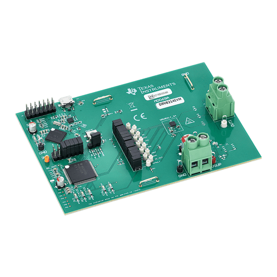
Description
The DRV821x or DRV823x evaluation module (EVM)
allows for easy evaluation of the DRV8213, DRV8214,
DRV8215, DRV8234, and DRV8235 devices. The
EVM has been programmed and configured to work
out of the box and begin spinning motors right
away. The EVMs showcase an integrated motor
driver with N-channel H-bridge, charge pump, current
sense output, current regulation, and protection
circuitry. The DRV8214 and DRV8234 integrate a
ripple counting technology that allows for sensorless
motor position monitoring, stall detection, and speed/
voltage regulation. The DRV8215 and DRV8235
integrate stall detection and speed/voltage regulation.
DRV8213 integrates stall detection. The charge pump
integrates all capacitors and allows for 100% duty
cycle operation. The EVM is accompanied by a GUI
application for easy control of the motor driver.
Get Started
1. Order the EVM
a.
https://www.ti.com/tool/DRV8213EVM
b.
https://www.ti.com/tool/DRV8214EVM
c.
https://www.ti.com/tool/DRV8215EVM
d.
https://www.ti.com/tool/DRV8234EVM
e.
https://www.ti.com/tool/DRV8235EVM
2. Use the web-based GUI here:
https://dev.ti.com/gallery/view/MotorDriversBSM/
DRV821x_DRV823x-EVM-GUI/.
SLVUCO1A – MAY 2023 – REVISED APRIL 2024
Submit Document Feedback
3. Connect USB and external power supply.
4. Launch DRV821x_DRV823x-EVM-GUI and select
the EVM variant on the home page.
Features
•
Onboard 3.3V LDO for digital voltage supply
•
eZ-FET lite USB-based on-board emulator for
ease of programming and debugging MSP430
microcontroller
•
Main signal header with removable shunts to
disconnect main signals going to the motor driver
IC from the MCU
•
GUI software to control EVM and DRV IC
Applications
•
Brushed DC motor, solenoid, & relay driving
•
Vacuum robot
•
Water
•
Electronic smart lock
•
Electronic and robotic toys
•
Infusion pumps and other portable medical
equipments
•
Electric toothbrush
•
Portable printers
•
Point-of-sale (POS) devices
•
Other battery powered DC motor applications
DRV8214EVM
Copyright © 2024 Texas Instruments Incorporated
and
gas meters
DRV821x and DRV823x Evaluation Module
Description
1
Advertisement
Table of Contents

Related Manuals for Texas Instruments DRV821 Series


Summary of Contents for Texas Instruments DRV821 Series
- Page 1 • Other battery powered DC motor applications https://www.ti.com/tool/DRV8234EVM https://www.ti.com/tool/DRV8235EVM 2. Use the web-based GUI here: https://dev.ti.com/gallery/view/MotorDriversBSM/ DRV821x_DRV823x-EVM-GUI/. DRV8214EVM SLVUCO1A – MAY 2023 – REVISED APRIL 2024 DRV821x and DRV823x Evaluation Module Submit Document Feedback Copyright © 2024 Texas Instruments Incorporated...
-
Page 2: Kit Contents
Table 1-1. Kit Contents ITEM QUANTITY One of DRV8213EVM, DRV8214EVM, DRV8215EVM, DRV8234EVM, or DRV8235EVM 3ft White USB-A to Micro-USB Cable DRV821x and DRV823x Evaluation Module SLVUCO1A – MAY 2023 – REVISED APRIL 2024 Submit Document Feedback Copyright © 2024 Texas Instruments Incorporated... -
Page 3: Specification
The documents in Table 1-2 provide information regarding Texas Instruments integrated circuits used in the assembly of the EVM. This user's guide is available from the TI web site under literature number SLVUCO1. Any letter appended to the literature number corresponds to the document revision that is current at the time of the writing of this document. - Page 4 EVM. Avoid touching the marked hot surface area when driving high currents to prevent potential burn damage. DRV821x and DRV823x Evaluation Module SLVUCO1A – MAY 2023 – REVISED APRIL 2024 Submit Document Feedback Copyright © 2024 Texas Instruments Incorporated...
- Page 5 Connector for programming MSP430F5528 used in the eZ-FET lite debugger circuit. Only used one time by PCB manufacturer to programmed eZ-FET lite debugger MCU. 3V3 LDO connector. SLVUCO1A – MAY 2023 – REVISED APRIL 2024 DRV821x and DRV823x Evaluation Module Submit Document Feedback Copyright © 2024 Texas Instruments Incorporated...
- Page 6 RC_OUT (not applicable to DRV8215EVM or DRV8235EVM): Ripple count pulse output from the driver. Corresponds to the ripples of the motor during commutation. • nFAULT: fault indicator output (LOW = fault detected; HIGH= no fault detected). DRV821x and DRV823x Evaluation Module SLVUCO1A – MAY 2023 – REVISED APRIL 2024 Submit Document Feedback Copyright © 2024 Texas Instruments Incorporated...
-
Page 7: Connector Information
Connect the motor terminals across OUT1 and OUT2. GND strip for grounding voltage probes and digital multimeter leads USB connector SLVUCO1A – MAY 2023 – REVISED APRIL 2024 DRV821x and DRV823x Evaluation Module Submit Document Feedback Copyright © 2024 Texas Instruments Incorporated... -
Page 8: Indicator Leds
STALL: OFF when no motor stall is detected by DRV. ON when motor stall is detected. nFAULT: OFF when no fault present. ON when DRV flags a fault. DRV821x and DRV823x Evaluation Module SLVUCO1A – MAY 2023 – REVISED APRIL 2024 Submit Document Feedback Copyright © 2024 Texas Instruments Incorporated... -
Page 9: Hardware Setup
4. Connect motor to output connector. 5. Set up is now complete. See Figure 2-6 for setup image. Figure 2-6. Hardware Setup SLVUCO1A – MAY 2023 – REVISED APRIL 2024 DRV821x and DRV823x Evaluation Module Submit Document Feedback Copyright © 2024 Texas Instruments Incorporated... - Page 10 Click on the title or blank space of the first search result to open the Web-Based GUI. Figure 3-1. TI GUI Composer Gallery Results for Launching or Downloading Local Installer DRV821x and DRV823x Evaluation Module SLVUCO1A – MAY 2023 – REVISED APRIL 2024 Submit Document Feedback Copyright © 2024 Texas Instruments Incorporated...
- Page 11 This needs to be done the first time the user sets up the EVM, as a software update can have been released since the EVM was initially programmed. Figure 3-3. Program Device SLVUCO1A – MAY 2023 – REVISED APRIL 2024 DRV821x and DRV823x Evaluation Module Submit Document Feedback Copyright © 2024 Texas Instruments Incorporated...
- Page 12 6. The GUI setup is now complete. The following section provides an overview of the GUI and how to use the GUI to control EVM. DRV821x and DRV823x Evaluation Module SLVUCO1A – MAY 2023 – REVISED APRIL 2024 Submit Document Feedback Copyright © 2024 Texas Instruments Incorporated...
-
Page 13: Gui Overview
IN1 and IN2 ramp rate. The PWM slowly ramps up or down the duty cycle to avoid sudden speed changes. The ramp rate is adjustable from 0-25 with 0=no ramp and 25=slowest ramp rate. SLVUCO1A – MAY 2023 – REVISED APRIL 2024 DRV821x and DRV823x Evaluation Module Submit Document Feedback Copyright © 2024 Texas Instruments Incorporated... - Page 14 Voltage Regualtion. These items can only be selected when the EN_OUT bit is 0, so set the Enable Outputs toggle to Disabled to modify these. See the device data sheet for more information about these modes. DRV821x and DRV823x Evaluation Module SLVUCO1A – MAY 2023 – REVISED APRIL 2024 Submit Document Feedback Copyright © 2024 Texas Instruments Incorporated...
-
Page 15: Quick Start
1. Input the motor resistance into the first box. Click How to measure motor resistance for a few ways to determine the resistance of the motor if not given in the motor data sheet. SLVUCO1A – MAY 2023 – REVISED APRIL 2024 DRV821x and DRV823x Evaluation Module Submit Document Feedback Copyright © 2024 Texas Instruments Incorporated... - Page 16 3. Repeat step 2 until the green check box is continuously showing, indicating the detected ripple speed closely matches the target speed. DRV821x and DRV823x Evaluation Module SLVUCO1A – MAY 2023 – REVISED APRIL 2024 Submit Document Feedback Copyright © 2024 Texas Instruments Incorporated...
- Page 17 KMC=168] or both work, then select the second option since KMC is larger. Figure 3-10. IPROPI and RC_OUT waveform after parameter tuning SLVUCO1A – MAY 2023 – REVISED APRIL 2024 DRV821x and DRV823x Evaluation Module Submit Document Feedback Copyright © 2024 Texas Instruments Incorporated...
- Page 18 TI does not recommended to change these under typical circumstances. DRV821x and DRV823x Evaluation Module SLVUCO1A – MAY 2023 – REVISED APRIL 2024 Submit Document Feedback Copyright © 2024 Texas Instruments Incorporated...
- Page 19 The H-bridge Response and nFault Response widgets configure how the H-bridge and nFAULT signal respond due to the ripple count value exceeding the ripple count threshold. SLVUCO1A – MAY 2023 – REVISED APRIL 2024 DRV821x and DRV823x Evaluation Module Submit Document Feedback Copyright © 2024 Texas Instruments Incorporated...
- Page 20 Another method is by opening the motor and counting the segments. Many small DC motors have two brushes and three commutator segments. DRV821x and DRV823x Evaluation Module SLVUCO1A – MAY 2023 – REVISED APRIL 2024 Submit Document Feedback Copyright © 2024 Texas Instruments Incorporated...
-
Page 21: Register Map
2. To recall the register configurations, click on the File tab and then the click Load Registers. Select the saved .json file to load the register values. SLVUCO1A – MAY 2023 – REVISED APRIL 2024 DRV821x and DRV823x Evaluation Module Submit Document Feedback Copyright © 2024 Texas Instruments Incorporated... - Page 22 Design Files from any EVM tool folder under the Design Files section. DRV8213EVM Hardware Files.zip for DRV8213EVM and DRV821x, DRV823x Hardware Files.zip for DRV8214, DRV8215, DRV8234, or DRV8235EVMs. DRV821x and DRV823x Evaluation Module SLVUCO1A – MAY 2023 – REVISED APRIL 2024 Submit Document Feedback Copyright © 2024 Texas Instruments Incorporated...
- Page 23 Unknown revision Assembly Variant: Sheet: warrant that this design will meet the specifications, will be suitable for your application or fit for any particular purpose, or will operate in an implementation. Texas Instruments and/or its Drawn By: Jacob Thompson File: MD069C.SchDoc...
- Page 24 PCB layers of the EVM. The Altium source files can be downloaded in the aforementioned Hardware Design Files for a given EVM. Figure 4-3. Top View Figure 4-4. Top Layer DRV821x and DRV823x Evaluation Module SLVUCO1A – MAY 2023 – REVISED APRIL 2024 Submit Document Feedback Copyright © 2024 Texas Instruments Incorporated...
- Page 25 Hardware Design Files Figure 4-5. Bottom View Figure 4-6. Bottom Layers SLVUCO1A – MAY 2023 – REVISED APRIL 2024 DRV821x and DRV823x Evaluation Module Submit Document Feedback Copyright © 2024 Texas Instruments Incorporated...
- Page 26 LED, Red, SMD LED_0603 150060RS75000 Wurth Elektronik D2, D4, D5, D6, D8 Green LED, Green, SMD LED_0603 150060VS75000 Wurth Elektronik DRV821x and DRV823x Evaluation Module SLVUCO1A – MAY 2023 – REVISED APRIL 2024 Submit Document Feedback Copyright © 2024 Texas Instruments Incorporated...
- Page 27 0402 CRCW040210R0FKED Vishay-Dale R66, R67 0402 RES, 680, 5%, 0.063 W, AEC-Q200 Grade 0, 0402 CRCW0402680RJNED Vishay-Dale 0402 SLVUCO1A – MAY 2023 – REVISED APRIL 2024 DRV821x and DRV823x Evaluation Module Submit Document Feedback Copyright © 2024 Texas Instruments Incorporated...
- Page 28 Shunt, 2.54mm, Gold, Black Shunt, 2.54mm, Black 60900213421 Wurth Elektronik SH-J11, SH-J12, SH- J19, SH-J29, SH-J31, SH-J32, SH-J33, SH- J34, SH-J36 DRV821x and DRV823x Evaluation Module SLVUCO1A – MAY 2023 – REVISED APRIL 2024 Submit Document Feedback Copyright © 2024 Texas Instruments Incorporated...
- Page 29 VM, VSUP Test Point, Multipurpose, Red, TH 36-5010-ND Keystone Electronics Testpoint Oscillator, 4MHz, 700ppm, 39pF, SMD 4.5x2mm CSTNR4M00GH5L000R0 MuRata SLVUCO1A – MAY 2023 – REVISED APRIL 2024 DRV821x and DRV823x Evaluation Module Submit Document Feedback Copyright © 2024 Texas Instruments Incorporated...
-
Page 30: Additional Information
Added support for DRV8213, DRV8214, and DRV8234..................• Added support for DRV8215 and DRV8235. Updated for GUI version 2.0.0............. DRV821x and DRV823x Evaluation Module SLVUCO1A – MAY 2023 – REVISED APRIL 2024 Submit Document Feedback Copyright © 2024 Texas Instruments Incorporated... - Page 31 STANDARD TERMS FOR EVALUATION MODULES Delivery: TI delivers TI evaluation boards, kits, or modules, including any accompanying demonstration software, components, and/or documentation which may be provided together or separately (collectively, an “EVM” or “EVMs”) to the User (“User”) in accordance with the terms set forth herein.
- Page 32 www.ti.com Regulatory Notices: 3.1 United States 3.1.1 Notice applicable to EVMs not FCC-Approved: FCC NOTICE: This kit is designed to allow product developers to evaluate electronic components, circuitry, or software associated with the kit to determine whether to incorporate such items in a finished product and software developers to write software applications for use with the end product.
- Page 33 www.ti.com Concernant les EVMs avec antennes détachables Conformément à la réglementation d'Industrie Canada, le présent émetteur radio peut fonctionner avec une antenne d'un type et d'un gain maximal (ou inférieur) approuvé pour l'émetteur par Industrie Canada. Dans le but de réduire les risques de brouillage radioélectrique à...
- Page 34 www.ti.com EVM Use Restrictions and Warnings: 4.1 EVMS ARE NOT FOR USE IN FUNCTIONAL SAFETY AND/OR SAFETY CRITICAL EVALUATIONS, INCLUDING BUT NOT LIMITED TO EVALUATIONS OF LIFE SUPPORT APPLICATIONS. 4.2 User must read and apply the user guide and other available documentation provided by TI regarding the EVM prior to handling or using the EVM, including without limitation any warning or restriction notices.
- Page 35 Notwithstanding the foregoing, any judgment may be enforced in any United States or foreign court, and TI may seek injunctive relief in any United States or foreign court. Mailing Address: Texas Instruments, Post Office Box 655303, Dallas, Texas 75265 Copyright © 2023, Texas Instruments Incorporated...
- Page 36 TI products. TI’s provision of these resources does not expand or otherwise alter TI’s applicable warranties or warranty disclaimers for TI products. TI objects to and rejects any additional or different terms you may have proposed. IMPORTANT NOTICE Mailing Address: Texas Instruments, Post Office Box 655303, Dallas, Texas 75265 Copyright © 2024, Texas Instruments Incorporated...
Need help?
Do you have a question about the DRV821 Series and is the answer not in the manual?
Questions and answers