Advertisement
www.ti.com
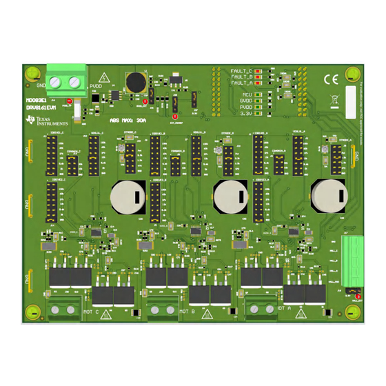
EVM User's Guide: DRV8161EVM
DRV8161 Evaluation Module
Description
The DRV8161EVM is a 30A, 3-phase brushless DC
drive stage using three DRV8161 gate drivers for
spinning BLDC motors.
The EVM allows quick evaluation of the DRV8161
device which spins a BLDC motor with trapezoidal
commutation and control.
Status LEDs for all power supplies as well as FAULT
LEDs for the drivers are included for user feedback.
The C2000
™
LaunchPad
is required for this kit and is required for this kit and
is used to control the DRV8161 drivers as well as to
monitor and report faults.
SLVUCY2 – APRIL 2024
Submit Document Feedback
™
(LAUNCHXL-F280049C)
DRV8161EVM
Copyright © 2024 Texas Instruments Incorporated
Features
•
8V to 20V Gate drive voltage with 8V to 90V drain
voltage suited for up to 48V applications
•
16mA-1A source and 32mA-2A sink current
settings
•
Integrated CSA's per half bridge driver for accurate
current sensing
Applications
•
Servo drives
•
Industrial and collaborative robot
•
Industrial mobile robot
•
Linear motor transport systems
•
Drones
•
E-bikes, e-scooters, and e-mobility
•
Industrial
and
appliances
•
12V, 24V and 48V automotive BLDC motor drives
Description
(AGV/AMR)
fans and pumps
DRV8161 Evaluation Module
1
Advertisement
Table of Contents

Related Manuals for Texas Instruments DRV8161EVM


Summary of Contents for Texas Instruments DRV8161EVM
- Page 1 EVM User's Guide: DRV8161EVM DRV8161 Evaluation Module Description Features The DRV8161EVM is a 30A, 3-phase brushless DC • 8V to 20V Gate drive voltage with 8V to 90V drain drive stage using three DRV8161 gate drivers for voltage suited for up to 48V applications spinning BLDC motors.
-
Page 2: Kit Contents
DRV8161 data sheet DRV816x 100V Half-Bridge Smart Gate Driver with Integrated Protection and Current Sense Amplifier (SLVSGZ1). This user's guide details the hardware implementation of the EVM and how to set up and power the board. The DRV8161EVM allows users to evaluate the performance of a DRV8161 motor driver. A LAUNCHXL-F280049C BoosterPack ™... -
Page 3: Specification
Evaluation Module Overview 1.3 Specification The DRV8161EVM can support voltages up to 48V and currents up to 30A. To prevent damage to both the IC and the EVM, confirm that these voltage and current specifications are not exceeded. 1.4 Device Information The DRV816x is a 100V half bridge driver with a gate drive power supply ranging from 8V–10V. - Page 4 DRV8161EVM when not in use. The DRV8161EVM is designed for an input supply from 8 VDC to 48 VDC and up to 30A continuous drive current (in-line fuse limited). The input connects to J16 with the noted polarity. PVDD_TP test point connects to the same node but must not be used for high current input.
- Page 5 The faults can be reset in the GUI software using the CLEAR FAULTS button. More details on the GUI can be found in Section 3.1. SLVUCY2 – APRIL 2024 DRV8161 Evaluation Module Submit Document Feedback Copyright © 2024 Texas Instruments Incorporated...
- Page 6 2-1. For more information on resistor to settings, please consult the data sheet. Setting Phase A Phase B Phase C IDRIVE 1 IDRIVE 2 CSAGAIN VDSLVL DTMODE DRV8161 Evaluation Module SLVUCY2 – APRIL 2024 Submit Document Feedback Copyright © 2024 Texas Instruments Incorporated...
- Page 7 (CSAGAIN_X) on the EVM using the jumper headers. Note The CSA Gain is fixed in SW for 40V/V . 5. Mate the DRV8161EVM onto the top half of the LAUNCHXL-F280049C (LaunchPad headers J1/J3 and J2/J4) as shown in Figure 2-2.
- Page 8 This section details the features of the EVM GUI Software. The GUI is written in GUI Composer and is available on the development software gallery at dev.ti.com/gallery. Figure 3-1. DRV8161EVM GUI Software The GUI connects and programs the C2000 MCU on the LAUNCHXL-F280049C board when launched, assuming the board is connected and powered.
- Page 9 EXT_CS AREF COMMON nFAULT_C 3.3V CSAREF 100nF COMMON R143 CSAREF_A 0.33uF UA78M33CDCYR SH-J18 R144 CSAREF_B CSAREF R145 CSAREF_C SH-J19 Figure 4-1. Schematic 1 SLVUCY2 – APRIL 2024 DRV8161 Evaluation Module Submit Document Feedback Copyright © 2024 Texas Instruments Incorporated...
- Page 10 R14 8 62.0k 3.30k 27.0k 100pF 100pF 1.30k 12.0k 10.0k 5.6k 2.0k SH-J14 SH-J15 DT cap placed close to I C Figure 4-2. Schematic 2 DRV8161 Evaluation Module SLVUCY2 – APRIL 2024 Submit Document Feedback Copyright © 2024 Texas Instruments Incorporated...
- Page 11 100V 0.005 1000pF 1000pF 1000pF R154 R155 R156 10.0 10.0 10.0 Net-Tie Net-Tie Net-Tie 100V 100V 100V 1000pF 1000pF 1000pF Figure 4-3. Schematic 3 SLVUCY2 – APRIL 2024 DRV8161 Evaluation Module Submit Document Feedback Copyright © 2024 Texas Instruments Incorporated...
-
Page 12: Pcb Layouts
Figure 4-4. EVM Dimensions Figure 4-6. EVM Top Layer Figure 4-7. EVM Signal Layer 1 Figure 4-8. EVM Signal Layer 2 Figure 4-9. EVM Bottom Layer DRV8161 Evaluation Module SLVUCY2 – APRIL 2024 Submit Document Feedback Copyright © 2024 Texas Instruments Incorporated... - Page 13 Hardware Design Files Figure 4-10. EVM Bottom Overlay SLVUCY2 – APRIL 2024 DRV8161 Evaluation Module Submit Document Feedback Copyright © 2024 Texas Instruments Incorporated...
- Page 14 GRT188R61E106ME13D CAP, CERM, 0.33uF, 25V, +/- 10%, X5R, 0805 08053D334KAT2A C41, C42, C43, C44 CAP, CERM, 0.1uF, 16V, +/- 5%, X7R, 0603 Kemet C0603C104J4RACTU DRV8161 Evaluation Module SLVUCY2 – APRIL 2024 Submit Document Feedback Copyright © 2024 Texas Instruments Incorporated...
- Page 15 RT0603BRD07130KL R49, R50, R64 R3, R4, R17, R27, R28, R41, RES, 62.0 k, 0.1%, 0.1 W, 0603 Susumu Co Ltd RG1608P-623-B-T5 R51, R52, R65 SLVUCY2 – APRIL 2024 DRV8161 Evaluation Module Submit Document Feedback Copyright © 2024 Texas Instruments Incorporated...
- Page 16 RES, 453 k, 0.5%, 0.1 W, 0603 Yageo America RT0603DRE07453KL RES, 23.2 k, 0.5%, 0.1 W, 0603 Yageo America RT0603DRE0723K2L R100 RES, 49.9 k, 1%, 0.1 W, 0603 Yageo RC0603FR-0749K9L DRV8161 Evaluation Module SLVUCY2 – APRIL 2024 Submit Document Feedback Copyright © 2024 Texas Instruments Incorporated...
- Page 17 CAP, CERM, 2200pF, 100V, +/- 10%, X7R, AEC-Q200 Grade CGA3E2X7R2A222K080AA 1, 0603 D4, D5, D6, D7, D8, D9 Diode, Zener, 5.6V, 500mW, SOD-123 Diodes Inc. DDZ5V6B-7 SLVUCY2 – APRIL 2024 DRV8161 Evaluation Module Submit Document Feedback Copyright © 2024 Texas Instruments Incorporated...
- Page 18 RES, 100 k, 5%, 0.1 W, AEC-Q200 Grade 0, 0603 Vishay-Dale CRCW0603100KJNEA R142, R149 RES, 0, 5%, 0.1 W, AEC-Q200 Grade 0, 0603 Vishay-Dale CRCW06030000Z0EA DRV8161 Evaluation Module SLVUCY2 – APRIL 2024 Submit Document Feedback Copyright © 2024 Texas Instruments Incorporated...
-
Page 19: Additional Information
Texas Instruments. Google Chrome ® is a registered trademark of Google LLC . All trademarks are the property of their respective owners. SLVUCY2 – APRIL 2024 DRV8161 Evaluation Module Submit Document Feedback Copyright © 2024 Texas Instruments Incorporated... - Page 20 STANDARD TERMS FOR EVALUATION MODULES Delivery: TI delivers TI evaluation boards, kits, or modules, including any accompanying demonstration software, components, and/or documentation which may be provided together or separately (collectively, an “EVM” or “EVMs”) to the User (“User”) in accordance with the terms set forth herein.
- Page 21 www.ti.com Regulatory Notices: 3.1 United States 3.1.1 Notice applicable to EVMs not FCC-Approved: FCC NOTICE: This kit is designed to allow product developers to evaluate electronic components, circuitry, or software associated with the kit to determine whether to incorporate such items in a finished product and software developers to write software applications for use with the end product.
- Page 22 www.ti.com Concernant les EVMs avec antennes détachables Conformément à la réglementation d'Industrie Canada, le présent émetteur radio peut fonctionner avec une antenne d'un type et d'un gain maximal (ou inférieur) approuvé pour l'émetteur par Industrie Canada. Dans le but de réduire les risques de brouillage radioélectrique à...
- Page 23 www.ti.com EVM Use Restrictions and Warnings: 4.1 EVMS ARE NOT FOR USE IN FUNCTIONAL SAFETY AND/OR SAFETY CRITICAL EVALUATIONS, INCLUDING BUT NOT LIMITED TO EVALUATIONS OF LIFE SUPPORT APPLICATIONS. 4.2 User must read and apply the user guide and other available documentation provided by TI regarding the EVM prior to handling or using the EVM, including without limitation any warning or restriction notices.
- Page 24 Notwithstanding the foregoing, any judgment may be enforced in any United States or foreign court, and TI may seek injunctive relief in any United States or foreign court. Mailing Address: Texas Instruments, Post Office Box 655303, Dallas, Texas 75265 Copyright © 2023, Texas Instruments Incorporated...
- Page 25 TI products. TI’s provision of these resources does not expand or otherwise alter TI’s applicable warranties or warranty disclaimers for TI products. TI objects to and rejects any additional or different terms you may have proposed. IMPORTANT NOTICE Mailing Address: Texas Instruments, Post Office Box 655303, Dallas, Texas 75265 Copyright © 2024, Texas Instruments Incorporated...
Need help?
Do you have a question about the DRV8161EVM and is the answer not in the manual?
Questions and answers