iWave iW-RainboW-G34D Hardware User's Manual
Hide thumbs
Also See for iW-RainboW-G34D:
- Hardware user's manual (62 pages) ,
- Quick start manual (17 pages) ,
- Hardware user's manual (55 pages)
Table of Contents
Advertisement
Quick Links
Advertisement
Table of Contents

Related Manuals for iWave iW-RainboW-G34D


Summary of Contents for iWave iW-RainboW-G34D
- Page 1 8M Mini or i.MX 8M Nano µQseven Development Platform Hardware User Guide iW-RainboW-G34D/G37D i.MX 8M Mini or i.MX 8M Nano Qseven Development Platform Hardware User Guide DRAFT VERSION SUBJECT TO CHANGE REL0.1 iWave Systems Technologies Pvt. Ltd. Page 1 of 73...
- Page 2 If you are not the intended recipient (or authorized to receive for the recipient), you are hereby notified that any disclosure, copying distribution or use of any of the information contained within this document is STRICTLY PROHIBITED. Thank you. “iWave Systems Tech. Pvt. Ltd.” REL0.1 iWave Systems Technologies Pvt.
- Page 3 No warranty of accuracy is given concerning the contents of the information contained in this publication. To the extent permitted by law no liability (including liability to any person by reason of negligence) will be accepted by iWave Systems, its subsidiaries or employees for any direct or indirect loss or damage caused by omissions from or inaccuracies in this document.
-
Page 4: Table Of Contents
2.9.3 Fan Header ............................58 2.9.4 JTAG Header (Optional).......................... 59 2.10 ......................61 ARRIER OARD XPANSION ONNECTORS 2.11 & IO H ......................62 ARRIER OARD OWER EADERS TECHNICAL SPECIFICATION ..........................65 REL0.1 iWave Systems Technologies Pvt. Ltd. Page 4 of 73... - Page 5 3.3.1 i.MX 8M Mini or i.MX 8M Nano Qseven Carrier Board Mechanical Dimensions ........68 3.3.2 Guidelines to insert the µQseven SOM into Carrier Board ............... 70 ORDERING INFORMATION ..........................72 REL0.1 iWave Systems Technologies Pvt. Ltd. Page 5 of 73...
- Page 6 -1........................70 IGURE Μ SEVEN NSERTION SOM I -2........................71 IGURE Μ SEVEN NSERTION SOM I -3........................71 IGURE Μ SEVEN NSERTION SOM I -4........................71 IGURE Μ SEVEN NSERTION REL0.1 iWave Systems Technologies Pvt. Ltd. Page 6 of 73...
- Page 7 18: P ........................... 66 ABLE OWER NPUT EQUIREMENT 19: P ........................66 ABLE OWER UTPUT PECIFICATION 20: E ........................67 ABLE NVIRONMENTAL PECIFICATION 21: O ....................... 72 ABLE RDERABLE RODUCT UMBERS REL0.1 iWave Systems Technologies Pvt. Ltd. Page 7 of 73...
-
Page 8: Introduction
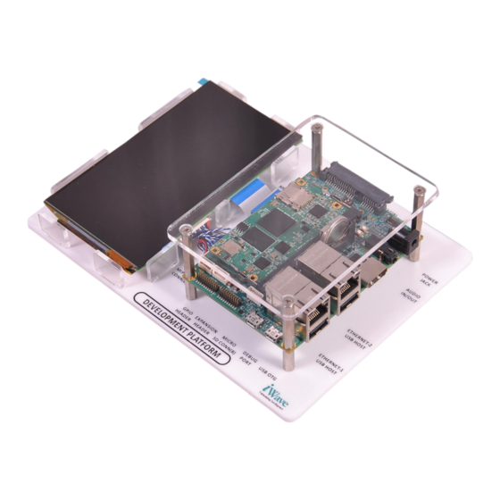
The µQseven is a versatile small form factor computer Module targeting applications that require low power, low cost and high performance. iW-RainboW-G34D/G37D Development Platform comes with Qseven Carrier board, and i.MX 8M Mini or i.MX 8M Nano based µQseven SOM. The development board can be used for quick prototyping of various applications targeted by the i.MX 8M Mini or i.MX 8M Nano processor. - Page 9 Real Time Clock SDIO Secure Digital Input Output SDHI SD Card Host Interface System on Chip System On Module UART Universal Asynchronous Receiver/Transmitter Universal Serial Bus USB OTG USB On The Go REL0.1 iWave Systems Technologies Pvt. Ltd. Page 9 of 73...
-
Page 10: Terminlogy Description
Note: Signal Type does not include internal pull-ups or pull-downs implemented by the chip vendors and only includes the pull-ups or pull-downs implemented on board. References • IMX8MMIEC_Rev_x.pdf • IMX8MNIEC_Rev_x.pdf • Qseven® Specification Version 2.1 • Qseven® Design Guide REL0.1 iWave Systems Technologies Pvt. Ltd. Page 10 of 73... -
Page 11: Architecture And Design - Qseven Carrier Board
This section provides detailed information about the i.MX 8M Mini or i.MX 8M Nano Qseven Development Platform features with high level block diagram and detailed information about each block. i.MX 8M Mini or i.MX 8M Nano Qseven Carrier Board Block Diagram iW-RainboW-G34D/G37D-i.MX 8M Mini or i.MX 8M Nano µQseven Development Kit Block Diagram Qseven MXM Connector... -
Page 12: I.mx 8M Mini Or I.mx 8M Nano Qseven Development Platform Features
Power & IO Header-1 ➢ I2C x 2 Ports ➢ GPIOs & Power • Power & IO Header-2 ➢ SPI (MSIOF0 with SS1#) x 1 Port ➢ WDOUT, WDTRIG# & Power REL0.1 iWave Systems Technologies Pvt. Ltd. Page 12 of 73... - Page 13 Qseven Edge connector, then JTAG can be tested in Qseven carrier board. In i.MX 8M Mini or i.MX 8M Nano SoC based µQseven SOM, JTAG is not supported in Qseven Edge connector by default. REL0.1 iWave Systems Technologies Pvt. Ltd. Page 13 of 73...
-
Page 14: Qseven Mxm Connector
This Qseven MXM Edge mating connector (J13) is physically located at the top of the board as shown below. Figure 2: Qseven MXM Connector REL0.1 iWave Systems Technologies Pvt. Ltd. Page 14 of 73... -
Page 15: Table 3: Qseven Mxm Connector Pin Out
GBE_MDI1+ GPHY_BTXRXP IO, DIFF Gigabit Ethernet MDI differential pair 1 positive. This pin is connected to RJ45 Magjack J21. GBE_MDI0+ GPHY_ATXRXP IO, DIFF Gigabit Ethernet MDI differential pair 0 positive. REL0.1 iWave Systems Technologies Pvt. Ltd. Page 15 of 73... - Page 16 Push button (SW3) in the carrier board used for SOM On/Off control. GPII1 GPII_1 O, 3.3V CMOS This pin is connected to Push button (SW7) in carrier board. P5 Output of SOM I/O Expander REL0.1 iWave Systems Technologies Pvt. Ltd. Page 16 of 73...
- Page 17 8M Nano µQseven SOM. This pin is connected from 8bit DIP switch (SW2)1 position in carrier board. SDIO_CLK# SD2_CLK SD2_CLK/W2 I, 3.3V CMOS SD2 Clock. This pin is connected to SD/MMC connector (J28). REL0.1 iWave Systems Technologies Pvt. Ltd. Page 17 of 73...
-
Page 18: Figure 14: Sd/Mmc Connector
This pin is connected to SD/MMC connector (J28) in carrier board. SDIO_DAT4 NC in i.MX 8M Mini ori.MX 8M Nano µQseven SOM. This pin is connected to SD/MMC connector (J28) in carrier board. REL0.1 iWave Systems Technologies Pvt. Ltd. Page 18 of 73... - Page 19 This pin is connected from )/AD13 I2S audio codec. SMB_ALERT# SMB_ALERT_B(GPIO1_ USB2_OTG_ This pin is connected to OC(GPIO1_I M.2 Key-B Connector-1 O15)/AB9 (J33) & Optionally connected to M.2 Key- B/Key-M Connector-2(J31) REL0.1 iWave Systems Technologies Pvt. Ltd. Page 19 of 73...
- Page 20 8M Nano µQseven SOM USB_6_7_OC# NC in i.MX 8M Mini or i.MX 8M Nano µQseven SOM USB_4_5_OC# USB_HUB4_OC O, 3.3V CMOS This pin is connected to USB3.0 Host Port1 Over REL0.1 iWave Systems Technologies Pvt. Ltd. Page 20 of 73...
- Page 21 USB HUB output port3 of the i.MX 8M Mini or i.MX 8M Nano SOM). USB_P2- USB_HUB2OUT_DM IO, DIFF USB 2.0 Host Port2 Data negative. This pin is connected to Dual stack USB3.0 TypeA REL0.1 iWave Systems Technologies Pvt. Ltd. Page 21 of 73...
- Page 22 8M Mini or i.MX 8M Nano SOM). USB_P1+ USB1_DP USB1_DP/B2 IO, DIFF USB 2.0 OTG Port1 Data positive. This pin is connected to Micro USB OTG connector (J1). REL0.1 iWave Systems Technologies Pvt. Ltd. Page 22 of 73...
- Page 23 LVDS Receiver. eDP1_TX1-/ I, DIFF LVDS LVDS_B1- eDP0_TX2+/ LVDS_CH2_P I, DIFF LVDS LVDS primary channel LVDS_A2+ differential pair2 positive. This pin is connected to LVDS Receiver. eDP1_TX2+/ I, DIFF LVDS LVDS_B2+ REL0.1 iWave Systems Technologies Pvt. Ltd. Page 23 of 73...
- Page 24 LVDS_A_CLK- differential Clock negative. This pin is connected to LVDS Receiver. eDP1_AUX-/ I, 1.8V LVDS LVDS_B_CLK- LVDS_BLT_CTRL GPIO_LVDS_BLT_CTRL SPDIF_TX/AF I, 3.3V CMOS/ LCD Panel Backlight /GP_PWM_OUT (GPIO5_03) 10K PU Control. REL0.1 iWave Systems Technologies Pvt. Ltd. Page 24 of 73...
- Page 25 TMDS_CLK- This pin is connected to HDMI connector (J25) in carrier board. USB_SSTX1+ Power Ground. Power Ground. DP_LANE1+/ HDMI_D1P I, TMDS HDMI differential data lane 1 positive. TMDS_LANE1+ REL0.1 iWave Systems Technologies Pvt. Ltd. Page 25 of 73...
- Page 26 HDMI_D2M I, TMDS HDMI differential data lane TMDS_LANE2- 2 negative. This pin is connected to HDMI connector (J25) in carrier board. HDMI_CTRL_CL I2C3_SCL I2C3_SCL/E1 I, 3.3V OD HDMI I2C Clock. REL0.1 iWave Systems Technologies Pvt. Ltd. Page 26 of 73...
- Page 27 (J31). Power Ground. Power Ground. PCIE3_TX+ PCIE3_RX+ PCIE3_TX- PCIE3_RX- Power Ground. Power Ground. PCIE2_TX+ PCIE2_RX+ PCIE2_TX- PCIE2_RX- UART0_TX UART2_TX(SAI3_TXC) UART2_TX(S I, 3.3V CMOS UART2 interface serial data AI3_TXC)/ transmitter. REL0.1 iWave Systems Technologies Pvt. Ltd. Page 27 of 73...
- Page 28 This pin is connected to M.2 Key-B/Key-M Connector(J31). PCIE0_RX- PCIE_RXN PCIE_RXN_N O, DIFF PCIe Channel0 Receive data / A19 input negative. This pin is connected to M.2 Key-B/Key-M Connector(J31). REL0.1 iWave Systems Technologies Pvt. Ltd. Page 28 of 73...
- Page 29 CAN transceiver. 190 LPC_FRAME#/ Q7_GPIO5(GPIO1_07) GPIO1_IO07/ IO,3.3VCMOS/ General purpose GPIO5 AF11 10K PU Input/Output5. This pin is connected to M.2 Key-B Connector (J33) and optionally connected to M.2 Key-B/Key-M Connector(J31). REL0.1 iWave Systems Technologies Pvt. Ltd. Page 29 of 73...
- Page 30 Power & IO Header-2 (J3) 1 Pin. 202 SPI_CS1# GPIO_ECSPI1_SS1 SAI5_MCLK/ I, 3.3V CMOS SPI Chip Select2. AD15 This pin is also connected to Power & IO Header-2 (J3) 2 Pin. REL0.1 iWave Systems Technologies Pvt. Ltd. Page 30 of 73...
- Page 31 210 MFG_NC3 JTAG_TMS JTAG_TMS/ O, 3.3V CMOS/ JTAG Test Mode Select. 10K PU This pin is connected from JTAG Header (J17) 07 through buffer. 211 VCC/NC 212 VCC/NC 213 VCC/NC REL0.1 iWave Systems Technologies Pvt. Ltd. Page 31 of 73...
- Page 32 O, 5V Power Supply Voltage. 229 VCC VCC_5V O, 5V Power Supply Voltage. 230 VCC VCC_5V O, 5V Power Supply Voltage. Note: 1. PCIe is not supported in i.MX 8M Nano SoC REL0.1 iWave Systems Technologies Pvt. Ltd. Page 32 of 73...
-
Page 33: On Board Switches
The i.MX 8M Mini or i.MX 8M Nano Qseven carrier board has power ON/OFF switch (SW1) to control the Main Power Input On/Off functionality. This power ON/OFF switch is physically located at the top of the board as shown below. Figure 3: Power ON/OFF Switch REL0.1 iWave Systems Technologies Pvt. Ltd. Page 33 of 73... -
Page 34: Board Configuration Switch
Board configuration switch are not used in i.MX 8M Mini or i.MX 8M Nano Development platform and so only the required bits are explained with default setting highlighted. REL0.1 iWave Systems Technologies Pvt. Ltd. Page 34 of 73... -
Page 35: General Purpose Berg-Stick
By pulling low on this pin puts i.MX 8M Mini or i.MX 8M Nano SoC in serial download mode where the CPU boot media can be programmed through its USB OTG interface. Figure 5: General Purpose Berg-Stick REL0.1 iWave Systems Technologies Pvt. Ltd. Page 35 of 73... -
Page 36: Reset Switch
8M Mini or i.MX 8M Nano SoC. “RSTBTN#” signal of Qseven MXM connector is directly connected from Reset Push button switch. This Reset Push button switch (SW4) is physically located at the top of the board as shown below. Figure 6: Reset Switch REL0.1 iWave Systems Technologies Pvt. Ltd. Page 36 of 73... -
Page 37: Serial Interface Features
The required debug interface can be selected by setting the 4 bit of Board configuration switch (SW2) to Debug UART Mode. REL0.1 iWave Systems Technologies Pvt. Ltd. Page 37 of 73... -
Page 38: Data Uart Header
3.3V Supply Voltage. UART2_TX(SAI3_TXC) I, 3.3V CMOS UART2 interface Receive signal. UART2_RX(SAI3_TXFS) O, 3.3V CMOS UART2 interface Transmit signal. RTS# UART2_RTS_B(SAI3_RXD) I, 3.3V CMOS UART2 interface Ready To Send signal. REL0.1 iWave Systems Technologies Pvt. Ltd. Page 38 of 73... -
Page 39: High Speed Interface Features
O, 3.3V Power 3.3V Supply Voltage. Power Ground. FULL_CARD_POWER_OF M.2_PWR_OFF# O, 3.3V CMOS M.2 Full card Power off Signal. F# (O)(0/1.8V_3.3V) 10K PU USB_D+ USB_HUB3OUT_DP IO, USB USB2.0 Host Port3 Data Plus. REL0.1 iWave Systems Technologies Pvt. Ltd. Page 39 of 73... - Page 40 O, 1.8V CMOS M.2 Dynamic Power Reduction 10K PU Signal. GPIO10_(W_DISABLE_2# /HSIC_STROBE(1.2V)) 10K PU (I/O)(0/1.8V) Power Ground. GPIO8(AUDIO3/I2S_WS)( I/O)(0/1.8V) PERN1/USB30_RX- /SSIC_RX- UIM-RESET (I) SIM_RST O, SIM SIM Card Reset Signal. PERP1/USB30_RX+/SSIC_ REL0.1 iWave Systems Technologies Pvt. Ltd. Page 40 of 73...
- Page 41 _15) )/(0/1.8V) Power Ground. GPIO3(SYSCLK/GNSS_0/ UIM_RST2) (I/O)(0/1.8V) PETN0/SATA_A- GPIO4(TX_BLK/GNSS_1/ UIM_PWR2)(I/O)(0/1.8V) PETP0/SATA_A+ PERST# (O)(0/3.3V) Power Ground. CLKREQ# (I/O)(0/3.3V) REFCLKN PEWAKE# (I/O)(0/3.3V) REFCLKP MFG_DATA Power Ground. MFG_CLOCK ANTCTL0 (I)(0/1.8 V) COEX3 (I/O)(0/1.8V) REL0.1 iWave Systems Technologies Pvt. Ltd. Page 41 of 73...
-
Page 42: Key-B/Key-M Connector-2
PCIe reference clock from Qseven MXM connector is connected to M.2 Key-B/Key-M Connector for clock reference. The M.2 Key-B/Key-M Connector(J31) is physically located on the bottom side of the board as shown below. REL0.1 iWave Systems Technologies Pvt. Ltd. Page 42 of 73... -
Page 43: Figure 10: M.2 Key-B/Key-M Connector
USB_HUB4OUT_DM IO, USB USB2.0 Host Port3 Data Minus. Note:This pin is NC if M.2 Key-M is used DAS/DSS M.2_LED_2 O, 3.3V CMOS Provide status indicators via LED. PETn3 Power Ground. REL0.1 iWave Systems Technologies Pvt. Ltd. Page 43 of 73... - Page 44 I2C3_SCL O, 1.8V CMOS I2C CLK. Note: I2C3_SCL is given to voltage translator SATA-B+/PERn0 PCIE_RXN I, DIFF PCIe Port 0 Receive pair negative. SMB_DATA I2C3_SDA IO, 1.8V CMOS I2C Data. REL0.1 iWave Systems Technologies Pvt. Ltd. Page 44 of 73...
- Page 45 Note: GPIO1_07 Optionally connected SUSCLK M.2_2_SUSCLK I, 3.3V CMOS M.2 Clock Note: Optionally connected 32.768kHz 33E Series Clock Oscillator. CONFIG_1 M.2_2_CONFIG_1 I, 3.3V CMOS M.2 Conn-2 Configuration Pin 1. 10K PU REL0.1 iWave Systems Technologies Pvt. Ltd. Page 45 of 73...
-
Page 46: Note: Pcie Is Not Supported In I.mx 8M Nano Soc
3.3 V9 VCC_3V3 O, 3.3V Power 3.3V Supply Voltage. CONFIG_2 M.2_2_CONFIG_2 I, 3.3V CMOS M.2 Conn-2 Configuration Pin 2. 10K PU Note: PCIe is not supported in i.MX 8M Nano SoC. REL0.1 iWave Systems Technologies Pvt. Ltd. Page 46 of 73... -
Page 47: Communication Interface Features
500mA. If connected USB2.0 device takes more than 500mA current, this power switch limits the current to constant mode and sends the over current indication signal to the over current indicator pin of Qseven MXM connector USB port 0 & 1 (86 Pin). REL0.1 iWave Systems Technologies Pvt. Ltd. Page 47 of 73... -
Page 48: Usb2.0 Port1 (Otg)
Qseven MXM connector USB port 0 & 1. This USB2.0 OTG connector is physically located at the top of the board as shown below. REL0.1 iWave Systems Technologies Pvt. Ltd. Page 48 of 73... -
Page 49: Sdio Port
This power enable/disable is controlled from the SDIO_PWR# pin of Qseven MXM connector. This SD/MMC connector (J28) is physically located at the bottom of the board as shown below. REL0.1 iWave Systems Technologies Pvt. Ltd. Page 49 of 73... - Page 50 8M Mini or i.MX 8M Nano µQseven Development Platform Hardware User Guide Figure 144: SD/MMC Connector REL0.1 iWave Systems Technologies Pvt. Ltd. Page 50 of 73...
-
Page 51: Can Header
Note: Optionally connected to on board 12V through resistor and not populated. CANL CANL IO, DIFF CAN Differential negative. Power Ground. CANH CANH IO, DIFF CAN Differential positive. Power Ground. REL0.1 iWave Systems Technologies Pvt. Ltd. Page 51 of 73... -
Page 52: Audio/Video Features
3.5mm Jack J7 and J8 correspondingly. Also, Headphone detect and Mic detect is supported through Qseven MXM connector pin 188 & 187 Pin correspondingly. These Audio Jacks are physically located at the top of the board as shown below. Figure 166: Audio IN/OUTJack REL0.1 iWave Systems Technologies Pvt. Ltd. Page 52 of 73... -
Page 53: 7" Lcd With Capacitive Touch
Table 10: 7” RGB LCD Connector Pin Out Signal Name Signal Type / Pin Name Description Termination O,3.3V CMOS/ Up or Down Scanning Direction. 10K PD O,3.3V CMOS/ Left or Right Scanning Direction. 10K PU REL0.1 iWave Systems Technologies Pvt. Ltd. Page 53 of 73... - Page 54 Qseven MXM connector which is i.MX 8M Mini or i.MX 8M Nano SOC’s GPIO pin “E14”. This Capacitive Touch Connector (J15) is physically located at the top of board as shown below. REL0.1 iWave Systems Technologies Pvt. Ltd. Page 54 of 73...
-
Page 55: Hdmi Port
8M Mini or i.MX 8M Nano Qseven carrier board supports HDMI display output through On-SOM MIPI_DSI to LVDS/HDMI Bridge “LT8912B” from Lontium semiconductor and is available on the TMDS port of the Qseven MXM REL0.1 iWave Systems Technologies Pvt. Ltd. Page 55 of 73... -
Page 56: Figure 19: Hdmi Connector
8M Mini or i.MX 8M Nano Qseven carrier board. HDMI connector (J25) is physically located on top of the board as shown below. Figure 19: HDMI Connector REL0.1 iWave Systems Technologies Pvt. Ltd. Page 56 of 73... -
Page 57: Additional Features
This coin cell voltage is connected to µQseven SOM for RTC back up voltage when VCC main power is off. This Coin Cell Holder (J35) is physically located at the bottom of the board as shown below. Figure 20: Coin Cell Holder REL0.1 iWave Systems Technologies Pvt. Ltd. Page 57 of 73... -
Page 58: Fan Header
Signal Name Description /Termination VCC_12V O, 12V Power 12V Supply Voltage. PWM2_OUT(I2C4_SCL) O, 3.3 CMOS Fan Speed control. Power Ground. TACHO FAN_PWR VCC_FAN O, Power Controlled Power for Fan. Power Ground. REL0.1 iWave Systems Technologies Pvt. Ltd. Page 58 of 73... -
Page 59: Jtag Header (Optional)
8M Mini or i.MX 8M Nano µQseven SOM and hence JTAG connector on i.MX 8M Mini or i.MX 8M Nano Qseven carrier board cannot be used for debugging. Figure 22: JTAG Header REL0.1 iWave Systems Technologies Pvt. Ltd. Page 59 of 73... -
Page 60: Table 13: Jtag Header Pin Out
10K PD Power Ground. JTAG_TDO JTAG_TDO O, 3.3V CMOS JTAG test data Output. Power Ground. RSTBN RSTBN I,3.3V CMOS/ Reset Signal. 10K PU Power Ground. Power Ground. 10K PD Power Ground. REL0.1 iWave Systems Technologies Pvt. Ltd. Page 60 of 73... -
Page 61: Carrier Board Expansion Connectors
8M Mini or i.MX 8M Nano µQseven Development Platform Hardware User Guide 2.10 Carrier Board Expansion Connectors Since SOM Expansion Connectors are not present, Carrier Board Expansion Connectors-1 and 2 are NC. Figure 23: Carrier Board Expansion Connectors REL0.1 iWave Systems Technologies Pvt. Ltd. Page 61 of 73... -
Page 62: Carrier Board Power & Io Headers
Supply Voltage 12V. VCC_5V Power Supply Voltage 5V. VCC_12V Power Supply Voltage 12V. VCC_5V Power Supply Voltage 5V. VCC_3V3 Power Supply Voltage 3.3V. VCC_3V3 Power Supply Voltage 3.3V. Power Ground. Power Ground. REL0.1 iWave Systems Technologies Pvt. Ltd. Page 62 of 73... -
Page 63: Table 15: Carrier Board Power & Io Header-2
Not used in i.MX 8M Mini or i.MX 8M Nano Qseven carrier board. Note: This pin is connected to Qseven MXM connector 70 pin. VCC_1V5 Power Supply Voltage 1.5V. Power Ground. Power Ground. REL0.1 iWave Systems Technologies Pvt. Ltd. Page 63 of 73... -
Page 64: Table 16: Carrier Board Power Header
8M Mini or i.MX 8M Nano µQseven Development Platform Hardware User Guide Table 16: Carrier Board Power Header Signal Type / Signal Name Description Termination Power Ground. VCC_3V3 Power Supply Voltage 3.3V. REL0.1 iWave Systems Technologies Pvt. Ltd. Page 64 of 73... -
Page 65: Technical Specification
This connector is physically placed at the top of the board as shown below. Figure 25: Power Jack Table 17: Power Jack Pin Out Signal Name Signal Type / Pin Name Description Termination VCC_12V 12V, Power Input Supply Voltage. Power Ground. Power Ground. REL0.1 iWave Systems Technologies Pvt. Ltd. Page 65 of 73... -
Page 66: Power Output Specification
Power to µQseven SOM (through Qseven MXM connector) VCC_5V_SOM 4.85V 5.15V 4000mA VRTC_3V0 2.8V 3.3V Power to Add-On Module (through Expansion connector3) VCC_5V 4.85V 5.15V 1500mA VCC_3V3 3.15 3.45 1000mA VCC_1V5 1.35 1.65 500mA REL0.1 iWave Systems Technologies Pvt. Ltd. Page 66 of 73... -
Page 67: Environmental Characteristics
3.2.3 Electrostatic Discharge iWave’s i.MX 8M Mini or i.MX 8M Nano Qseven Development Platform is sensitive to electro static discharge and so high voltages caused by static electricity could damage some of the devices on board. It is packed with necessary protection while shipping. -
Page 68: Mechanical Characteristics
Carrier Board mechanical dimension is shown below. (All dimensions are shown in mm) Figure 26: i.MX 8M Mini or i.MX 8M Nano Qseven Carrier board Mechanical dimension – Top View REL0.1 iWave Systems Technologies Pvt. Ltd. Page 68 of 73... -
Page 69: Figure 27: I.mx 8M Mini Or I.mx 8M Nano Qseven Carrier Board Mechanical Dimension - Bottom View
Please refer the below figures for height details of the i.MX 8M Mini or i.MX 8M Nano Qseven Carrier Board. Figure 28: i.MX 8M Mini or i.MX 8M Nano Qseven Carrier board Mechanical dimension – Top Max Heighted Components REL0.1 iWave Systems Technologies Pvt. Ltd. Page 69 of 73... -
Page 70: Guidelines To Insert The Μqseven Som Into Carrier Board
Make sure that the Notch position of µQseven module is proper while inserting. Figure 30: μQseven SOM Insertion Step -1 • Insert M2.5x12mm pan head screw from i.MX 8M Mini or i.MX 8M Nano Qseven carrier board bottom side as shown below. REL0.1 iWave Systems Technologies Pvt. Ltd. Page 70 of 73... -
Page 71: Figure 31: Μqseven Som Insertion Step -2
8M Mini or i.MX 8M Nano μQseven SOM into the carrier board through the M2.5mm screw as shown below. Figure 32: μQseven SOM Insertion Step -3 • Finally, tighten the M2.5mm nut into screw as shown below. Figure 33: μQseven SOM Insertion Step -4 REL0.1 iWave Systems Technologies Pvt. Ltd. Page 71 of 73... -
Page 72: Ordering Information
Commercial i.MX8M Nano Quad, 1GB LPDDR4, 8GB eMMC flash, Linux Kit without display Note: For Development platform identification purpose, Product part number is pasted as Label with Barcode readable format. REL0.1 iWave Systems Technologies Pvt. Ltd. Page 72 of 73... - Page 73 8M Mini or i.MX 8M Nano µQseven Development Platform Hardware User Guide REL0.1 iWave Systems Technologies Pvt. Ltd. Page 73 of 73...
Need help?
Do you have a question about the iW-RainboW-G34D and is the answer not in the manual?
Questions and answers