2N Lift8 User Manual
Communicator for lifts
Hide thumbs
Also See for Lift8:
- User manual (377 pages) ,
- Brief manual (17 pages) ,
- Brief manual (13 pages)

Related Manuals for 2N Lift8


Summary of Contents for 2N Lift8
- Page 1 ® Lift8 Communicator for lifts User manual Firmware 2.2.0 Version 2.2.0 www.2n.cz ...
- Page 2 ...
- Page 3 The 2N TELEKOMUNIKACE a.s. is the holder of the ISO 9001:2009 certificate. All development, production and distribution processes of the company are managed by this standard and guarantee a high quality, technical level and professional aspect of all our...
-
Page 4: Product Description
® In this section, we introduce the Lift8 product, outline its application options and highlight the advantages following from its use. Here is what you can find in this section: 1.1 Product Description 1.2 Components and Associated Products 1.3 Upgrade 1.4 Terms and Symbols Used... -
Page 5: System Diagram
System Diagram ® Figure: Example of Lift8 Central Unit, Splitter and Audio Unit Connection Main bus Audio unit bus... -
Page 6: Components And Associated Products
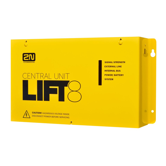
The audio units cannot be connected to a telephone line without the When shared by multiple shafts, the audio units cannot be connected without the CU and splitters. ® 918600 2N Lift8 Central Unit ® Figure: 2N Lift8 Central Unit For connection of up to 8 lifts to a GSM/UMTS/PSTN line. - Page 7 Audio unit electronics for lift cabin building in. Including speaker and microphone (HandsFree). Connection terminals for all prescribed elements and door opening signal input (optional). ® 918610EX 2N Lift8 Audio Unit – COP – Cable Version Contains LED, microphone and speaker connected to cables. ®...
- Page 8 ® 918611E 2N Lift8 Audio Unit – Machine Room/Control Centre ® Figure: 2N Lift8 Audio Unit – Machine Room/Control Centre Audio unit for the machine room/control centre. Contains receiver (optional) and keypad for easy control. Makes it possible to communicate with other system audio units and configure the withou t a PC.
- Page 9 ® 918613E 2N Lift8 Audio Unit – Compact ® Figure: 2N Lift8 Audio Unit – Compact Robust, heavy-duty design. Standard-sized ALARM button including signage for the blind and backlit pictograms (hardened glass). Easy cabin wall mounting. Easy 2-wire connection.
- Page 10 Figure: 2N Lift8 Audio Unit – Fireman Used for fire fighting operations. Activates top priority calls. ® 918610FZK 2N Lift8 Audio Unit – Fireman DPS (1 button) ® 918619E 2N Lift8 Audio Unit – Fireman DPS (knob + 1 push-to-talk button)
- Page 11 Lift8 Audio Unit – Fireman DPS Used by fire fighting operations. Activates top priority calls. 918617E 2N® Audio Unit - Shaft Antivandal Obrázek: 2N® Lift8 Audio Unit - Shaft Antivandal A robust, highly resistant audio unit designed for installation on lift cabin roofs and shaft bottoms, under cabin floors and/or any other places that require communication, e.g.
- Page 12 Contains logical inputs and switch relays. 918622 2N® Lift8 Camera Module Figure: 2N® Lift8 Camera Module For camera connection (IP, RS232, RS485) to the lift cabin. Every cabin in each shaft can contain a camera module (up to 8 camera modules in 2N® Lift8).
- Page 13 918654E 2N® Lift8 RS232 Module Obrázek: 2N® Lift8 RS232 Module The RS232 module connects the 2N® Lift8 system with the lift control unit. The lift control unit transmits a command via RS232 to the Central Unit for processing and executing.
- Page 14 ® 918651E 2N Lift8 UMTS Module ® Figure: 2N Lift8 UMTS Module For Central Unit connection via a mobile network. Optional data connection for remote system configuration. ® 918652E 2N Lift8 PSTN Module ® Figure: 2N Lift8 PSTN Module For Central Unit connection via an analogue line.
-
Page 15: Cooperating 2N Applications
® 918653E 2N Lift8 VoIP Module ® Figure: 2N Lift8 VoIP Module For Central Unit connection via a VoIP line. ® Cooperating 2N Applications ® 918700E 2N Lift8 Service Tool ® Figure: 2N Lift8 Service Tool ® Lift8 Service Tool... - Page 16 ® 918700E 2N Lift8 Control Panel ® Figure: 2N Lift8 Control Panel ® Lift8 Control Panel application is intended for administration of users, lifts and authorisations. ® 918700E 2N Lift8 Communicator ® Figure: 2N Lift8 Communicator ® Lift8 Communicator application...
-
Page 17: Associated 2N Products
® Lift8 Server application processes check calls and mediates communication between the s and PC applications. ® Associated 2N Products ® 918655E – 2N Lift8 External Pictograms Driver ® Figure: 2N Lift8 External Pictograms Driver ® Transforms the Lift8 cabin LED outputs into universal pilot lamps. - Page 18 P Improvements in applications Firmware 1.7.0 Camera module New protocols: CPC Antenna/KONE 2N ext. and P100 2N ext. (shaft number 1.7.0 and audio unit type identification) DE language support Auto-delete of archive records Firmware 1.8.0 1.8.0 Modified Groups menu in the Control Panel PT language support Firmware 1.9.0...
-
Page 19: Terms And Symbols Used
1.4 Terms and Symbols Used Symbols Used The following symbols and pictograms are used in the manual: Safety Always abide by this information to prevent persons from injury. Warning Always abide by this information to prevent damage to the device. Caution Important information for system functionality. - Page 20 2.1 PSTN/GSM/UMTS/VoIP Central Unit Description Figure: Central Unit Figure: Central Unit Indication Elements...
- Page 21 Figure: Central Unit Connectors There are a USB connector and reset button to the right of the (see the figure below). Figure: USB Connector and Reset Button...
-
Page 22: Before You Start
Reset Button Function Reset equipment – press the button quickly. Restore factory values – press and hold the button until all the LEDs turn red. Then release the button and wait until the SYSTEM LED flashes yellow. Now press the button quickly to delete all the user settings. -
Page 23: Cu Electrical Installation
1 battery connecting cables 1 brief manual 1 warranty sheet drilling template CU Mounting It is recommended to install the in a room that is secured against unauthorised persons, such as the lift machine room, switching station etc. On an easily accessible place there is a risk of telephone line misuse or SIM card misappropriation . -
Page 24: Power Supply
2N® Lift8 is not protected against dangerous touch and water - IP00 Make sure before installation that the 2N® Lift8 board is not damaged! Do not connect a power supply other than the allowed one to avoid electric accident or device damage. -
Page 25: Rechargeable Batteries
Rechargeable Batteries Caution ® If backup rechargeable batteries are used for the Lift8 power supply, the required backup of up to 1 h is guaranteed only if up to 20 audio units are connected in the system. The required 1h backup is not guaranteed if more than 20 audio units are installed. -
Page 26: Audio Units - Splitter (Cu) Bus Connection
Main bus 1 … Main bus power + 2 … Main bus power - 3 … Main bus audio + 4 … Main bus audio - 5 … Main bus data + 6 … Main bus data - Caution 6-wire Use unshielded wires of the cross-section of 0.75 mm . - Page 27 Safety The bus is electrically isolated from the telephone line circuits according to the EN60950 standard requirements and its low voltage cannot cause any electrical accident. Termination Resistance Connect the termination resistance connector to the first and last device connected to the bus: CU, splitter or I/O module.
-
Page 28: Examples Of Connection
Examples of Connection:... -
Page 29: Cu Connection To Telephone Network
VoIP PSTN ® Lift8 works in a broad band regardless of polarity and line parameters (refer to Technical Parameters). Connect it using the enclosed cable with an RJ–12 terminal. It is the most reliable and simplest connection. The disadvantage is the operating cost (fixed fee). -
Page 30: Other Recommendations
Other recommendations ® Notify the telephone network provider of your Lift8 installation and submit certification upon request. Your follow-up wiring must comply with the relevant safety regulations. You are recommended to secure your cabling against pirate connection (with a telephone lock, e.g.). - Page 31 Operation without SIM card or PSTN line ® Lift8 can be used as an intercom without an inserted SIM card or connected PSTN line during the lift fitting time. In this case do not enable the lift blocking function until the telephone line is connected.
-
Page 32: Electrical Installation
4 … Main bus audio - 5 … Main bus data + 6 … Main bus data - Warning ® Maintain the connection polarity to avoid a Lift8 error. Bus Connection between Audio Unit s and Splitter Interconnect the splitter and a udio unit s using a two-wire bus maintaining polarity. - Page 33 Lift blocking is enabled by the contact breaking (opening) when there is a telephone line (PSTN, ® GSM, UMTS, VoIP) fault or if the Lift8 rechargeable batteries are almost flat. Connect the contact to the relevant input of the control electronics of the lift/group of lifts. The control electronics must ensure that, after the contact opening, the lifts in operation go down to the nearest station and the doors open.
- Page 34 Figure: Termination Resistance Off...
-
Page 35: Mounting Types
Mounting Types See below for the mounting types and necessary components. Install the device on sites not exposed to water leakage or condensation. Wall Mounting Use appropriate wall plugs and screws for mounting (not included in the delivery). Hang the device using the pre-drilled holes on the device bottom. - Page 36 2.3 Audio Unit – COP Description The user does not come into a direct contact with this product. The control and indication elements depend on the specific installation. The functions of the indication elements correspond to the applicable standards Figure: Audio Unit – COP Caution - diodes Alarm call The yellow LED is illuminated to indicate the call setup progress (request...
-
Page 37: Before You Start
Before You Start Installation Conditions The panel has to be installation-ready, including speaker perforation. The panel has to be equipped with the following obligatory elements: ALARM button; illuminated pictogram “Request received”; illuminated pictogram “Connection made”. The above mentioned elements have been located as required by the applicable regulations. There must be free space of at least 65×130×25 mm behind the panel. -
Page 38: Separate Microphone Mounting
Figure: Mounting Hole Dimensions for Audio Unit – COP To mount the audio unit , you need 4 electrically spot welded screws, a sufficiently perforated speaker area and a microphone hole. In emergency, you can fix the audio unit on a perfectly degreased surface with a high-quality double-sided foam self-adhesive tape. -
Page 39: Frequently Asked Questions About Speaker
While gluing the speaker choose such procedures or adhesives that prevent membrane damage by adhesives and volatile substances or heat. We recommend you to keep the speaker sealed to eliminate vibrations and provide electrical insulation. Frequently Asked Questions about Speaker Is it possible to use a common speaker for the communicator and floor announcer No, it is not possible. - Page 40 Note If external LEDs are connected to connectors 7 and 8, LED indicators 1 and 2 will not be shining. Audio Unit L ocation Configuration audio unit is configured as a cabin audio unit by default and so it is not necessary to change the configuration.
-
Page 41: Bus Connection
Figure: Address Configuration for Audio Unit – COP Caution In versions 2.0.0 and higher, up to 7 audio unit positions can be configured for two-cabin lifts (1 - cabin roof, 2 - cabin = default, 3 - under cabin, 4 - shaft bottom, 5 - cabin 2 roof, 6 - cabin 2, 7 - under cabin 2). -
Page 42: Alarm Button Connection
Warning ® The audio unit is intended for 2N Lift8 audio unit bus connection exclusively. Do not connect it to other wires to avoid its damage or destruction. Maintain polarity while connecting the audio unit to avoid audio unit error. -
Page 43: Cancel Input Connection (Door Contact, Optional)
CANCEL Input Connection (Door Contact, Optional) This input helps cancel a rescue request if the lift is fully functional. When the ALARM button is pressed, the system waits for a pre-programmed period of time, which is a little longer than the maximum lift running time. -
Page 44: Led Indicator Connection
Description ® The device transforms the Lift8 Car Unit LED outputs into a universal pilot lamp, whose outputs are capable of driving two lamps rated at the maximum of 36 Volts, 0.5 Amps. The outputs are galvanically isolated from the Car Unit. Since the lamp outputs are polarity independent, both AC and DC power supplies can be used for powering the lamps. -
Page 45: Wiring Diagram
Caution External pictograms are connected to connectors 7 and 8 on the cabin audio unit. ® The manufacturer, 2N TELEKOMUNIKACE a.s., hereby declares that the Lift8 Exter nal Pictogram Driver is in compliance with the essential requirements and other relevant provisions of the 1999/5/EC Directive. -
Page 46: Induction Loop Connection
The yellow LED keeps shining on the audio unit. ® The service technician enters a valid password via the Lift8 voice menu to terminate the process. When the rescue password is entered via the voice menu, the yellow LED goes off on the audio unit and the 'Rescue process was terminated' is played. -
Page 47: Operation
Caution - upgrade The yellow, green and red LEDs are on (request received, connection confirmed and red LED under the glass) to indicate audio unit initialisation. The yellow and green LEDs flash to indicate audio unit upgrading. The red LED is permanently on. - Page 48 Before You Start Requirements Connect a handset supplied by the manufacturer to the audio unit to avoid handset operation error. Product Completeness Check Check the product for completeness before installation. 1 audio unit 2 wall plugs 2 wall plug screws 7–8 jumpers for common machine room configuration Mounting audio unit...
-
Page 49: Handset Connection
Make sure that the polarity is maintained. Warning ® The audio unit is intended for 2N Lift8 audio unit bus connection exclusively. Do not connect it to other wires to avoid its damage or destruction. Maintain polarity while connecting the audio unit... - Page 50 Caution Use the trimmer to set the best acoustic properties eliminating feedback. Volume configuration only works in the HandsFree mode. 2.5 Audio Unit – Shaft Description This audio unit is designed for installation on the lift shaft bottom or lift cabin roof, or wherever it is necessary to communicate (during lift maintenance, e.g.).
-
Page 51: Product Completeness Check
Operation This type of audio unit is operated by qualified people (lift maintenance staff, e.g.) Push the TRIPHONY button to activate voice communication with the other audio units of the same lift. Push the ALARM button, for example, when someone falls down the shaft. audio unit calls the numbers configured in the ALARM memory –... -
Page 52: Audio Unit Location Configuration
Warning ® The audio unit is intended for 2N Lift8 audio unit bus connection exclusively. Do not connect it to other wires to avoid its damage or destruction. Maintain polarity while connecting the audio unit to avoid audio unit error. - Page 53 Caution If the handset is not connected, the audio unit works in the HandsFree mode. A handset other than that supplied by the manufacturer may not work. Volume Configuration Open the protective door on the audio unit and adjust the volume using the trimmer.
- Page 54 Figure: Description of Audio Unit – Cabin Compact Operation Push the ALARM button to activate the audio unit. The 'Establishing connection' symbol goes on. The 'Connection established' symbol goes on when communication is set up. Before You Start Requirements Make sure that the lift wall is even. Make sure that the installation meets the standard requirements (ALARM button height and distance from the other lift buttons, e.g.).
- Page 55 Mounting Just drill holes into the cabin wall as shown in the figure below (also see the 1:1 figure on the product box). The larger hole is intended for cabling. Round the hole edges to avoid cable damage! Figure: Mounting Hole Dimensions for Audio Unit – Cabin Compact Note: Two 2.5 mm holes in the symbol window are intended for installations without access to the back side of the installation panel.
-
Page 56: Description Of Terminals
Warning ® The audio unit is intended for 2N Lift8 audio unit bus connection exclusively. Do not connect it to other wires to avoid its damage or destruction. -
Page 57: Rotary Switch
Connectors Figure: Connectors on Audio Unit – Cabin Compact (New Type) Safety Make sure that the minimum button isolation distance is 1.5 mm and breakdown voltage is 1,500 V. The button contacts may not be connected to any other circuits. If you cannot meet these conditions, use voltage control. -
Page 58: Alarm And Cancel Setting (Rotary Switch)
Procedure Rotary switch position Figure 1. Insert the hexagonal spanner (included) in the hole Position 1 – ALARM normal, on the product bottom edge CANCEL normal, cabin (window lock screw) and turn left (about 10 times) until you feel resistance. 2. -
Page 59: Volume Setting
Use the trimmer to set the best acoustic properties eliminating feedback. Mounting Completion ® Having connected the wires, you can complete the Lift8 wall mounting. If you can access the cabin wall from the outside, use the mounting type that prevents dismantling and unauthorised tampering from the cabin. Mounting procedure: Where access from the outside is possible, use the four pre-drilled M4 holes in the corners. -
Page 60: Connection Of Induction Loop For Hearing-Impaired
Tilt the window forwards and remove it. ® Now you have access to two holes in the window corners. Put Lift8 on the pre-drilled lift cabin wall holes and fit it with the included screws, which are suitable for plywood, chipboard, laminated plastic etc. - Page 61 1. Keep the CU disconnected from the mains. 2. Loosen the three screws on the upper cover of the CU 3. Move the upper cover of the in such a way that you can remove it. 4. When removing the cover, proceed with caution, be careful about the earth wire connecting the cover with the CU bottom part.
- Page 62 Warning While fitting the module, make sure that all the pins are fitted correctly into the connector to avoid module damage. 2.8 GSM/UMTS Module Description of Connection The module should be part of the Central Unit (hereinafter referred to as CU). If the CU does not contain the GSM/UMTS module, proceed as follows: 1.
-
Page 63: Voip Module
9. Now insert the SIM card and connect the antenna. Warning While fitting the module, make sure that all the pins are fitted correctly into the connector to avoid module damage. Caution In places with a poor signal quality find an appropriate place or use a special (directional) antenna. - Page 64 While fitting the module, make sure that all the pins are fitted correctly into the connector to avoid module damage. Caution In Lift8 is only supported codec A-Law 2.10 Audio Unit – Fireman The Fireman audio unit is available in two versions.
-
Page 65: Description: 1-Button Version
2.10.1 Fireman PCB 2.10.2 Fireman 2.10.3 Fireman – Mechanical Mounting 2.10.1 Fireman PCB Description: 1-Button Version The Fireman audio unit improves the fire fighting operations by setting up top priority calls between the Fireman audio unit and the cabin and machine room audio units in one and the same lift shaft. If any of the machine room audio units is configured as the control centre (intercom), you can join in the Fireman call. - Page 66 Install the Fireman audio unit in a dedicated space that can be easily accessed by firemen. The Fireman call has the highest priority, suspending all the other calls (refer to Function Description Press the detent button switch or turn the knob (0 > 1) to set up the Fireman call. The call duration is infinite.
-
Page 67: Electronic Installation
3 board-slid terminals, see the photo 1 board-mounted jumper (defining the button version) 1 mounting panel 1 speaker (directly or cable connected) 1 microphone (directly or cable connected) 1 printed cover Mounting Electronic Installation This audio unit is designed for mounting behind the lift control panel. Prepare the panel for installation as shown below: Figure: Cabin Audio Unit –... -
Page 68: Frequently Asked Questions Concerning Speaker
Separate Microphone Mounting If the microphone is supplied separately on a 25×25 mm large board with self-adhesive foil and with a cable, you can mount it easily behind any hole in the panel (keep the minimum hole diameter of 5 mm or a group of smaller holes of the same total area). - Page 69 Electric Installation Description of Terminals, Connectors and Jumpers Figure: Terminals, Connectors and Jumpers on Cabin Audio Unit – Universal Board Terminals Connectors Audio unit bus Unconnected Unconnected Unconnected (1-button version) Microphone connector (optional) Fireman call activation – with detent (2-button version) Unconnected Induction loop connector Activation/Deactivation –...
- Page 70 Warning ® The audio unit is intended for 2N Lift8 audio unit bus connection exclusively. Do not connect it to other wires to avoid its damage or destruction. Maintain polarity while connecting the audio unit to avoid audio unit error.
-
Page 71: Description: Knob+Button (Push-To-Talk)
Install the Fireman audio unit in a dedicated space that can be easily accessed by firemen. The Fireman call has the highest priority, suspending all the other calls (refer to Function Description Press the button (without detent) to set up the call. The call duration is infinite. Repress the button to stop the call. - Page 72 Install the Fireman audio unit in a dedicated space that can be easily accessed by firemen. The Fireman call has the highest priority, suspending all the other calls (refer to Function Description Turn the knob (0 > 1) to activate the Fireman call. The call duration is infinite. Return the knob to stop the call.
- Page 73 You can join in the Fireman call from a machine room audio unit configured as the intercom. Before You Start Product Completeness Check ® Please check the Lift8 Fireman package for completeness before starting installation: ® 1 2N Lift8 Fireman 1 double Torx 10 / Torx 20 ®...
-
Page 74: Bus Connection
® The audio unit is intended for 2N Lift8 audio unit bus connection exclusively. Do not connect it to other wires to avoid its damage or destruction. Keep polarity while connecting the audio unit to make the audio unit work properly. -
Page 75: Mechanical Mounting - Mounting Types
A wrong mounting procedure may deteriorate the Fireman's water resistance and damage the electronics due to water leakage. ® Lift8 Fireman is assembled with stainless steel screws. Using different, lower-quality screws may lead to screw and surface corrosion! 2.10.3 Fireman – Mechanical Mounting Mechanical Mounting –... -
Page 76: Flush Mounting - Thermally Insulated Wall
What you need for installation Properly cut-out hole or, optionally, a flush mounting kit, Part No. 9151001 ® Lift8 Fireman Covering frame: contact your distributor Flush Mounting – Thermally Insulated Wall What you need for installation Longer screws (depending on the thermal insulation thickness) ®... -
Page 77: Common Mounting Principles
What you need for installation Flush mounting kit for plasterboard, Part No. 9151002 ® Lift8 Fireman Covering frame: contact your distributor Caution The warranty does not cover any defects or failures of the product arisen as a result of improper mounting in contradiction to these instructions. -
Page 78: Flush Mounting - Classic Bricks
Warning Eliminate the risk of injury! Wall mounting is not suitable for narrow passages and places where people pay attention to something else. The manufacturer shall not be held liable for injuries caused by such negligence! Caution Wall mounting is a problem where the device may be damaged by vandals. In that case, use steel fitting elements instead of the plugs and screws included in the delivery. - Page 79 Drill a hole using the template included for all the necessary cables. Be careful while drilling as this type of mounting does not allow to balance rather great deviations later! Unpack the frame, put the audio unit onto it and put this set on the hole to test whether the hole is deep enough and its uneven edge is completely covered by the frame.
-
Page 80: Flush Mounting - Hollow Bricks
Flush Mounting – Hollow Bricks It is practically impossible to fit plugs into hollow bricks because the inner brick walls are too thin for drilling. Therefore, use the flush mounting kit and follow the instructions included therein. -
Page 81: Flush Mounting - Plasterboard
Flush Mounting – Plasterboard Use the flush mounting kit for plasterboard walls and follow the instructions included therein. 2.11 I/O Module Description The purpose of the I/O Module is to interconnect the Central Unit (CU) with the lift signalling. It is designed for usage of binary inputs or switching of relay inputs. - Page 82 Figure: I/O Module – Lower Side Figure: I/O Module – Upper Side Electrical Installation Caution Local power is not supported. Do not connect any local power supply. The main bus power is sufficient for the I/O Module.
- Page 83 6 … Main bus data - Warning ® Maintain the connection polarity to make the Lift8 system work correctly. Warning The bus is electrically isolated from the telephone line circuits according to the EN60950 requirements and its low voltage cannot cause any electrical accident.
-
Page 84: Address Setting
Address Setting Use a 10-pin rotary switch 0–9 (see the figure above) to set the I/O Module address for a lift. Set 1–8 like the shaft number for the splitter (set 5 for lift 5, e.g.). Warning Do not set address 0 and 9 to avoid system error. LED Indicators The I/O Module is equipped with ten LED indicators: two I/O Module status signalling LEDs, four input status signalling LEDs and four output status signalling LEDs. -
Page 85: Output Relay Connection
Output Relay Connection Every I/O Module is equipped with 4 bistable relays with the maximum load of 250 V / 5 A per contact. Never exceed this limit to avoid system damage. When the relay is closed, the respective ® LED signals this state. -
Page 86: Camera Module
Figure: Wall Mounting DIN Rail Mounting Mount the device on a standard TS 35 DIN rail. The recommended DIN rail length is 14 cm. Figure: DIN Rail Mounting Caution The warranty does not cover any defects or failures of the product arisen as a result of improper mounting in contradiction to these instructions. -
Page 87: Electric Installation
® Connect the camera module to the CU or splitter via a 2-wire bus to support the Lift8 communi cation. Connect a local power supply to record images on the microSD card. Caution - upgrade The red ERR LED is illuminated, the green OK LED flashes quickly and the yellow REL LED flashes slowly to indicate the upgrading process. -
Page 88: Mode Switch
Connect the camera module to the LAN if the IP camera is installed in the LAN. If the camera module is connected to the Lift8 system, use the Service Tool for configuration (refer to Subs. 5.3 - Service Tool - Use for more details). - Page 89 Direct IP camera - camera module connection...
-
Page 90: Ip Camera Lan Connection
IP camera LAN connection Select Set static IP address to a camera to activate the DHCP server to assign the defined address to the camera. If the static IP address is already set for the IP camera, it is unnecessary to enable the server. - Page 91 Caution The RS232 and RS485 cameras work without a local power supply too in the Lift8 system only if they have a low current consumption. Saving files to an SD card does not work without a local power supply.
-
Page 92: Camera Module Setting
The camera module can be used autonomously without being connected to Lift8 ® To make the module work autonomously, change the connection mode to autonomous (no 2N Lift8 connection) using a rotary switch (switch to 1), connect a local power supply, insert a microSD card and make basic configuration. - Page 93 Caution You are recommended to format the microSD card before inserting it in the camera module (FAT32). You are recommended to connect the camera module to a backup power supply to avoid recording errors at power outage. Connect the IP camera to the backup power supply too.
-
Page 94: Ip Camera Settings
IP Camera Settings (camera.cfg) Value Parameter name Default value Note range 1=RS-232 2=RS-485 Camera type 3=IP camera 1=160x80 2=320x240 Resolution 3=640x480 Compression ratio 10%-100% Image compression Each camera has a Camera URL IP http://10.0.0.1/jpg/image.jpg different URL. Camera recording Record interval 1s-3600s interval Record rotate file interval... -
Page 95: Standalone Camera Module Upgrade
(not respecting the upper/lower case). Standalone Camera Module Upgrade ® Refer to 2N Lift8 Camera Module at www.2n.cz for the latest firmware (ln_app_camera.bin). Download the file to a microSD root directory. When you insert the microSD card, the file (ln_app_camera.bin) will be loaded onto the dataflash (yellow LEDs flashing) and then the module will get restarted. - Page 96 User name: Admin Password: 2n...
- Page 97 Caution You can only change the web access password via the web and password.cfg. The username is always the same (Admin, regardless of lower/upper case). If the RS232 and RS485 cameras are connected, you cannot get connected to the camera module web interface. Download the recorded files in the Video files section.
- Page 98 Obrázek: DIN Rail Mounting Caution The warranty does not cover any defects or failures of the product arisen as a result of improper mounting in contradiction to these instructions. A wrong mounting procedure may lead to damage to the electronics due to water infiltration.
- Page 99 Before You Start Product Completeness Check Check whether the product package is complete before installation. The RS232 module package contains: 1 electronics board (RS232 module) 2 long threaded spacers, 1 short screwed spacer 1 screw RS232 cable cable bushing...
-
Page 100: Description Of Connection
Description of Connection Keep the disconnected from the mains. Loosen the three screws on the upper cover of the Move the upper cover in such a way that you can remove it. While removing the cover, proceed with caution - be careful about the earth wire connecting the cover with the bottom part. -
Page 101: Supported At Commands
To mount the RS232 cable, remove the blank module on the CU bottom edge. Put a cable bushing on the RS232 cable and insert it in the empty space (the cable bushing is factory-cut in one point for easier handling). Replace the rechargeable batteries and cover and tighten the 3 screws to fit the cover. -
Page 102: Serial Port Configuration
Caution Use a with the GSM/UMTS module for sending SMS. Serial Port Configuration You can only set the transmission rate of 9600-115200 bauds for the serial port. The other parameters are preset: Bits per word 8 bits Parity no parity Stop bits 1 stop bit 2.14 Audio Unit –... - Page 103 Product Completeness Check Check the product package for completeness before installation: ® 1 2N Lift8 Shaft Antivandal 1 Torx 10 / Torx 20 double-ended spanner Bushings (extra package): 1 big two-hole, sealed bushing with nut 1 replaceable big one-hole bushing seal for thick cables...
-
Page 104: Desription Of Terminals, Connectors And Jumpers
Desription of Terminals, Connectors and Jumpers Figure: Audio Unit - Fireman Terminals, Connectors and Jumpers Terminals and Connectors speaker connector 2 microphone connectors audio unit bus lockable button connector (knob) volume control configuration jumper button connector (push to talk) servicing connector Audio Unit Location The audio unit is designed for shaft bottom installations by default. -
Page 105: Volume Control
Warning ® The audio unit is intended for 2N Lift8 audio unit bus connection exclusively. Do not connect it to other wires to avoid its damage or destruction. Maintain polarity while connecting the audio unit to avoid audio unit error. - Page 106 An improper mounting may result in the audio unit not being waterproof. Water leakage may damage the electronics. ® Lift8 Shaft Antivandal is assembled with stainless steel screws. If you lose them, never use other screws to avoid corrosion and screw appearance deterioration!
- Page 107 2N TELEKOMUNIKACE a.s. Modřanská 621, 143 01 Prague 4, Czech Republic Phone: +420 261 301 500, Fax: +420 261 301 599 E-mail: sales@2n.cz Web: www.2n.cz D-2144 v1...
-
Page 108: Access To Programming Mode
® ® This section describes the Lift8 configuration. There are three ways how to program 2N Lift8 3.1 Lift8 Programming 3.2 Table of Parameters (FW 2.2.0) 3.3 SMS Configuration 3.1 Lift8 Programming ® The advantage of the Lift8 (hereinafter referred to as ) system is that it is programmed via where all the parameters are stored. -
Page 109: Programming Procedure
Programming Procedure Having entered the programming mode, you can change any programmable value(s) in any order. Proceed as follows: enter the function number and then the value. Use an asterisk as a separator or Enter. In general, the function has the following format: function number value The function number has three digits (see the table). -
Page 110: Programming Via Service Tool
the machine room or PSTN programming attempts fail too, you have probably entered an invalid password. Programming via Service Tool ® Refer to the Service Tool section (Section 5) for details. - Page 111 3.2 Table of Parameters (FW 2.2.0) Table of Parameters Par. Parameter Range of values Default Note Info name value Set 1 – ALARM up to 16 button memory empty digits: 0–9 Set 1 – ALARM up to 16 button memory empty Entering characters digits: 0–9...
- Page 112 Antenna, 4= CPC KONE, 5 = P100, 6 = autodetection DTMF protocol (CPC Antenna/P100), 7 = CPC Antenna 2N ext, 8 = CPC KONE 2N ext, 9 = P100 2N 1.6.0 - 2N ext is a protocol that Range transmits the shaft Set 1 –...
- Page 113 1-second pause while up to 16 Checking call programming is possible empty memory 3 ® digits: 0–9 via a PC (use the 2N Service Tool up to 16 Checking call empty memory 4 digits: 0–9 up to 16 If the set of checking call...
- Page 114 16 1-second pause while Error call empty programming is possible memory 4 digits: 0–9 ® via a PC (use the 2N up to 16 Service Tool Error call empty memory 5 digits: 0–9 up to 16 Error call...
- Page 115 Default output state of IO ABCD empty Find these parameters in module 8 the Configuration / IO modules / Basic menu in 2N® Service Tool From In 100 mAh units (x*100 version Battery 1–740 mAh "13=1.3 Ah, 740=74 capacity Ah") 1.6.0...
- Page 116 1 = perform dial tone tone detection detection. No call is set up 1.9.0 if the dial tone is not detected. 2N® Lift8 waits for the Time for tone constant or dialling tone. If detection after 1000–9999 ms 5000 ms...
- Page 117 This applies to PSTN modules only. If the line is OK, the test is carried out every hour. Lift8 seizes the line and tries to detect the dialtone. If no dialtone is detected, the line test is Max. telephone 1–20 s...
- Page 118 Private mode allows muting of the microphone on the 2N® Lift1. Possible setting of this parameter 0 – two way audio enabled always. 1 – X, no password in the rescue mode, time window when two way audio is enabled after success alarm call.
- Page 119 Cautions: Control centre User messages (outgoing) up to 10 recorded into the with message ® the aid of the 2N sequence by announcements in Service Tool pressing 3 after sequence call confirmation up to 10 Call end announcements in...
- Page 120 Rescue up to 16 digits: Set the rescue terminating empty password 0–9 password. 0 = disabled From 1 = An audio test of version Enable audio 0–1 selected audio units is unit self-test carried out after a check 1.10.0 call. 0 = standard connection, 1 = connect up to 4 cabin Enable 4-lift...
- Page 121 1.7.2 Set the time zone (UTC) in 1150 Time zone -12–12 which 2N® Lift8 installed. ** 1.8.0 Change value From Define how often 2N® version Synchronisation 1151 60–86400 3600 Lift8 shall synchronise period with the SNTP server. ** 1.7.2 Enable SNTP From synchronisation.
-
Page 122: Configuration By Computer
(refer to 7.1 Control Panel 1230 Client enabled 0–1 for details). ** 1.7.2 Range change From version Server IP Set the 2N® Lift8 Server 1231 empty address IP address. ** 1.6.0 From Specify the ports where version 1232 Server port 1–65535... -
Page 123: Function Description
Warning The SMS configuration function is supported only on condition that the CU is equipped with a (918650E 2N® Lift8 GSM Module) or UMTS (918651E 2N® Lift8 UMTS Module) module. This function is not available with the PSTN (918652E 2N® Lift8 PSTN Module) or VoIP (918653E 2N®... -
Page 124: Reset Command
SMS-based configuration obeys the same rules and limitations as configuration via an application or a phone (maximum length, value range, two-digit limitation, etc.). If any of these rules is not met, 2N® Lift8 shall not set the parameters and shall send an error SMS specifying the wrong parameter. -
Page 125: Meaning Of Pictograms (Icons)
Note The language localisation of the SMS reply is based on the voice menu recorded. Cs and en texts are available at present. Slovak uses cs, the other languages use en. In this section there is a description of the basic and expanded functions of the product. Here is what you can find in this section: 4.1 User Instructions 4.2 Control Centre Instructions... -
Page 126: Control Centre Instructions
4.2 Control Centre Instructions ALARM Call Press the ALARM button on any audio unit to make 2N® Lift8 call the control centre (refer to Automatic Dialling for details). A received call is either confirmed as configured (parameters 111–116 > Confirmation mode for memory 1–6 ALARM call –... -
Page 127: Incoming Call Voice Menu
2N® Lift8 via a PSTN, GSM, UMTS or VoIP network. Note The 9 selection serves primarily for 2N® Lift8 configuration – refer to S. 3 - Configuration. Tone Dialling Control during Call – Long Command List Where automatic dialling with confirmation is used, it is possible to use tone dialling for 2N®... -
Page 128: Function Description (For Advanced Users)
2N® Lift8 2N® Lift8 mutes the played-back announcement and, optionally, sends the identification code (DTMF). The call goes on until the timeout end and any of the following commands may be used. -
Page 129: Check Call
Machine Room Voice Menu Press 0 to dial the public telephone network Press lift number X to dial the lift Press 1 to dial the lift cabin Press 2 to dial the cabin roof Press 3 to dial the lift cabin bottom Press 4 to dial the shaft bottom Press 5 to dial the m... -
Page 130: Call Sequencing
Incoming Call Voice Menu Welcome, this is a 2N Lift 8 communicator Press 0 to dial the last-calling audio unit Enter the lift number X to dial another audio unit Press 1 to dial the lift cabin Press 2 to dial the cabin roof... -
Page 131: Call End (Outgoing/Incoming)
The timeout for call confirmation expired (see parameter 913 setting). The configured maximum call time has been exceeded (parameter 912). 10 seconds before the expiry, 2N® Lift8 plays “Caution, the call is ending” for you to extend the call with symbol has been received. -
Page 132: Evaluation Of Situations In Dialling With Confirmation
(due to inability to recognise the busy tone, e.g.). In general, DTMF is the most reliable type of signalling and so is used for confirmation. Thus, the connection is established (yet for a shorter time than usual) even in extreme cases, e.g. when 2N® Lift8 cannot identify the DTMF. -
Page 133: Dtmf Protocol Autodetection (Cpc/P100)
If such troubles occur, we recommend you to change the CPC Antenna/P100 (3/5) settings. 7,8,9. CPC (Antenna and KONE), P100 2N ext (for Alarm Calls only) The protocols work identically like for CPC (items 3 and 4) and P100 (item 5). The only difference is that they transmit shaft numbers and audio unit types too. - Page 134 – the lift gets blocked when the internal bus gets disconnected. 2N® Lift8 is off – the lift gets blocked immediately. Caution The PSTN line test is carried out every hour. If an error is detected, the line test is repeated every 2 minutes until the line is evaluated OK again.
-
Page 135: Normal 8-Lift Connection
Warning Make sure that each audio unit is assigned a different type (cabin roof, cabin, cabin bottom, shaft bottom). Note You can use a shaft audio unit instead of the cabin one. Normal 8-Lift Connection If you set parameter 994 to 0, you can connect up to 8 lift shafts and up to 5 audio unit s to each shaft (machine room, cabin roof, cabin, cabin bottom, shaft bottom). - Page 136 Figure: Connection two-cabin lift.
-
Page 137: Intercom Function
ALARM button on any audio unit (except for the machine room audio unit as the control centre) to start the process. Upon the press, 2N® Lift8 calls the pre-set machine room – control centre audio unit Press (for longer than 2 s) to answer an incoming call. -
Page 138: System Completeness Check Enable
Note ® If no audio units, splitters, etc. are connected in the Lift8 system, the INTERNAL BUS LED red light is flashing even if no system completeness check is being performed. System Completeness Check Enable Use the RESET button to set the function. -
Page 139: Audio Unit Audio Test
5.1 Installation and Login ® After the installation is launched, the installation program will scan your PC for another 2N Lift8 Service Tool version and ask you to uninstall the currently available version if identical with the new one. - Page 140 650 MB of free disk space at least. ® Now the Lift8 Service Tool is ready for use. Click the shortcut item on the desktop (see the figure below) or select the Start item to start the application. ® Figure:...
- Page 141 Enter the correct values. Refer to the text ® below for the default values. Now connect the and click Connect. The Lift8 Service Tool tomatically finds the connected on the PC and starts downloading parameters and logs. Having ®...
-
Page 142: Introduction To Application
Click the option to find the driver in the PC. ® Click the option to select a driver from a list and select a 2N Lift8 model instead of Complex USB device. Now the driver starts working and, whenever you connect the Central Unit to the same PC USB port, the device will be detected correctly. - Page 143 2N TELEKOMUNIKACE a.s. company improve the software quality, availability and performance within the applicable law. You can participate in this cooperation voluntarily and cancel your prior approval any time.
- Page 144 Figure: Maximum Application Display with Real-Time Device State The SIM card section specifies the SIM card state and IMSI and ICCID identifiers. The GSM Module section displays the GSM/UMTS module information: Module manufacturer, Module type, Module FW version and IMEI. Battery is devoted to the rechargeable batteries.
- Page 145 Figure: Real-Time Device State for VoIP Module Caution The Real-time device state only displays the Link properties and Battery. The other parts are displayed automatically depending on the HW connected. The lower part of the application includes the Logout button (to the right) and other important controls, which may be different in different menus.
-
Page 146: Basic Controls
Basic Controls New helps you create a new table of parameters. The existing table will be replaced after a warning. Open from file helps you read the table of parameters from a disk file. Save to file helps you save the current table of parameters into a disk file. Connect device switches the user into the 'Connect to device' menu. - Page 147 Disconnect device logs out the currently logged-in user from the Find (CTRL+F) enables search in the log. Set the string (word) to be searched in the window. Find next helps you find another occurrence of the set string (word). Read from device downloads the current settings and logs from the Save to device helps you save new parameters into the memory.
- Page 148 Load from directory helps you load the list of user messages from a directory to a disk. Save to directory saves the list of user messages into a selected folder onto a disk. Print HW setup - diagram helps you print out the current 2N® Lift8 settings as an image.
- Page 149 ® Print HW setup - text helps you print out the current Lift8 HW settings as a text. Upgrade starts FW uploading to the Refresh updates the list of connected communicators and the bus. Zoom in helps you get a close-up view of the diagram displayed.
- Page 150 ® configuration menu. The Parameters – Basic menu includes the table of all the Lift8 paramet ers including their codes. Refer to Subs. 3.2 . for the list of parameters and their meanings. All the parameters are arranged in associated groups for convenience.
- Page 151 Figure: Left – Inactive Filter, Right – Active Filter Each column with the funnel symbol includes filter settings; see the figure below. The Contains function finds the searched string in all the column items and returns all the occurrences. Enter a text into the string field and click Filter to activate the filter and find all the searched items in the column.
- Page 152 Figure: Cameras Menu The two buttons in the right-hand upper corner of the frame are active when the camera module is online. The pencil icon (Edit) is active even if the camera module is disconnected. Use Edit to switch to the camera module configuration menu. The camera icon helps you get the current image from the camera.
- Page 153 Figure: IP Camera Configuration Figure: RS232 Camera Configuration Press OK to confirm the settings and add the values to the table. Click Save to device to store the data in the memory and use it in the CU. Caution Caution! Whenever you click Save to device, the whole configuration table will be overwritten.
-
Page 154: Io Modules - Basic
Figure: Camera Window IO Modules - Basic Open the IO Modules menu to configure the IO modules. There are 8 frames in the window, one for each IO module on the given address. Each frame includes an IO module icon, which symbolises the module state, plus the module number and state description. - Page 155 Figure: IO Modules - Basic Menu The pencil icon (Edit) in the right-hand upper corner of the frame is active even if the camera module is disconnected. Click Edit to open a new window - IO module configuration. Like in the overview, the IO module state is displayed in the upper part of the window.
- Page 156 the outputs. Select Notification to enable/disable the notification pop-up window. Tick Beep to enable sending of the dialtone to your system output (speakers/headset) whenever a new notification...
-
Page 157: Io Modules - Actions
message arrives. Find Custom beep in the left-hand bottom corner. Click Select to select an audio file from your disk to be played as notification, or press Remove to remove the user file and start using the default sound again. IO Modules - Actions Actions menu helps you set the actions/commands to be executed. - Page 158 To edit a script of your own, first select the Active checkbox to disable the current graphical parameters and enable your own script settings. Programming should be made by a duly trained person. Refer to faq.2n.cz r examples. Having completed editing, click Verify to check the code entered.
- Page 159 Figure: Events Menu When an event is detected, you can specify a list of tasks to be performed: Activation, Deactivation, Send SMS, Send system SMS and Error call. Activation activates the relay contacts. Select more parameters in the extended settings to the right: module number on which the relay state change occurs, output number including description for better orientation and task duration.
-
Page 160: Logs - Advanced Settings
Figure: Logs Menu Save the captured log for later analysis in the left-hand bottom part. Click Find to find a message in the log. Enter the string to be searched in the dialogue window. Click Filter to find the first occurrence and Find next to find the next occurrence. - Page 161 Figure: Advanced Settings Menu Save configuration and Upload configuration help you save and load your advanced settings respectively onto your PC disk for later use. Bus Logs This menu has been introduced specifically for monitoring all communication along the bus between the bus-connected devices and the Central Unit.
- Page 162 E_drop_ack Count of discarded reply confirmations (duplicate confirmations) Player The Player menu helps save records of the cameras connected to the 2N® Lift8 camera modules onto SD cards inserted in the camera modules. You have three options how to play a video record.
-
Page 163: User Messages
User Messages helps you replace the default system announcements with user messages. Load ® these messages from a file or, in the correct format, via the Lift8 Service Tool. Use the microphone connected to your PC to record the messages. - Page 164 Figure: User Messages – Messages Menu The message list includes the message duration and two action buttons: Import message from file and Delete. If a message is not recorded, its total time is 0:00. The total time is displayed for each message recorded.
-
Page 165: Recording Settings
. Having selected the items, click Upgrade to ® make the Lift8 Service Tool load the new FW and voice menu into the Caution Having upgraded the FW you will be notified of the restart. - Page 166 . Enter a greater portion of the IMSI code to specify the SIM cards to be used in one network. You can add up to 10 IMSI codes to the licence. ® Contact your Lift8 supplier or the manufacturer's Technical Support department ( sales@2n.cz for the licence file.
-
Page 167: Connected Units
Connected units menu provides a graphic diagram of all the units connected to 2N® Lift8. following controls are available: Refresh to update the display, Press HW setting (diagram/text) to print out the diagram/text of all the Audio Units and splitters connected to the given CU. The diagram displays the units like in the application and the text provides the same information as the diagram in the XML format. - Page 168 IO Modules Figure: IO Modules Menu IO Modules menu helps you monitor the states of the IO modules connected. The IO modules section displays all the modules connected to the bus. Each module is identified with a number, which corresponds to its HW address set on the DPS. Furthermore, states of all the inputs and outputs are included.
-
Page 169: Installation And Licensing
If you click NO, your configuration will be preserved. Installation ® After the application is launched, the installation program will scan your PC for another 2N Lift8 Server version and ask you whether or not to uninstall the currently available version if any. If you deny, the installation wizard will be terminated. - Page 170 Minimum operating system requirements: Windows Vista, 7, 8 Licensing ® All the Lift8 Server functions are subject to licence. Upon your first PC installation of the application, you will get a trial licence for 800-hour operation and 50-user and 50-lift (CU) connection.
- Page 171 ® Having received the licence file, start the Lift8 Licence Tool and enter the path to this file into the Licence path parameter. Click Upload to add the licence to the server directory and restart the server to update the licence data.
-
Page 172: Database Export/Import
Caution ® Important! A default user with administrator login is created during the 2N Lift8 Server installation to get connected to the server and configure the other users. The default user uses the following login data: Name: Admin Password: 2n... -
Page 173: Setting Options
Enter the following command to stop the server: C:\Program Files\2N TELEKOMUNIKACE\ 2N Lift8\Server\l8-config.exe –cStopServer Then enter the –cImportDatabase parameter and the file path to import the database: C:\Program Files\2N TELEKOMUNIKACE\ 2N Lift8\Server\l8-config.exe –cImportDatabase "C:\ProgramData\2N TELEKOMUNIKACE\ 2N Lift8\Server\db–20130221095921–export.xml"... - Page 174 Here is what you can find in this section: 7.1 Installation and Login 7.2 Introduction to Application 7.3 Use ® Refer to the Lift8 product pages at www.2n.cz, download section, for the latest FW version. You can use this link from the online manual.
- Page 175 7.1 Installation and Login ® After the application is launched, the installation program will scan your PC for another 2N Lift8 Control Panel version and ask you to uninstall the currently available version if identical with the new one. Use the system Control Panel Add or Remove programs to uninstall the existing product version for reinstallation or reconfiguration.
- Page 176 If you have installed the application for the first time, the default connection will be created automatically. This connection cannot be removed. If you use one and the same PC for ® your Lift8 Control Panel and server, you can make use of these pre-settings and click the ® Connect icon. The Lift8 Control Panel will log in to the local server.
- Page 177 ® button. The application will execute login to the Lift8 Server Server login may take some time if you have an extensive database as the application has to download all the current tables. Be patient please and wait for completion.
- Page 178 The Setting submenu includes a Statistics window: confirm the request to enable transmission of your system data and software use surveys to help the 2N TELEKOMUNIKACE a.s. company improve the software quality, availability and performance within the applicable law. You can participate in this cooperation voluntarily and cancel your prior approval any time.
- Page 179 The Status line displays connection information. From the left: 'Connected to' includes the name of the server to which you are currently connected, 'IP' specifies the IP address of the server to which you are currently connected and the server listening port, and 'Current user' displays the currently logged in user.
- Page 180 Basic Controls New server helps you create a new connection in the login screen. New group helps you create a new server connection group in the login screen. Delete selected deletes the currently selected objects from the list in the login screen.
- Page 181 Create role adds a user role to the server configuration. Create user card adds a user in the Configuration/Users menu. Create group helps you create a new group of users/intercoms depending on which menu view is currently switched on. Add plan helps you add a building plan to the selected storage.
- Page 182 Configuration main menu where you can find almost all the Lift8 ettings. The user may access the menus allowed by its role. The Administrator can administer the whole system without limitations: divide users into groups, assign the user roles, assign the users intercoms to be configured and monitored, set the Call server for intercom check calls and configure the storages for buildings plans.
- Page 183 Figure: Intercoms Menu The list in the figure above includes some information on the intercom. The icon at each intercom indicates the lift cabin and can have several functions and meanings, which can be combined (see the table below).
- Page 184 Name. The so-created intercom is marked as unauthorised to eliminate unintentional calls ® (telemarketing, e.g.). To authorise this intercom, use the Basic tab for this intercom in the 2N Control Panel , which informs you that a new record has been created by a call from number x and asks you whether you want to keep it in the database or delete it.
- Page 185 Figure: Authorisation of Intercom Created by Check Call Complete more intercom card parameters for authorisation. See below for details (Intercoms). Note If the device that is making the check call for the first time supports the CPC or P100 protocol, you have to set this parameter manually. Calls from a number that is not included in the database are always served by the server by sending DTMF 5 and hang-up.
- Page 186 ® identification. Lift8 makes check calls from this number and Lift8 Server makes active check calls to this number: enter either a SIM card in the , number of the PSTN line to the intercom or number of the PBX/gateway behind which the intercom is located.
- Page 187 P100 Complete the serial number of your intercom in the Serial number field. Together with Password, this parameter is relevant for a correct function of the data tunnel. The default password is 2n. Click Save ® to confirm the setting. If you select the...
-
Page 188: Checking Calls
® Checking Calls menu includes a table of all the check calls received by the Lift8 Server om intercom addition until now. Click the filter button at each column to use filtration for call history search. Refer to the Calls subsection for details. The table provides the following information: check... -
Page 189: Alarm Calls
Alarm Calls ® Alarm Calls menu includes a table of all the alarm calls received by the Lift8 Server from intercom addition until now. Click the filter button at each column to use filtration for call history search. Refer to the Calls subsection for details. The table provides the following information: alarm... -
Page 190: Local Plan
Figure: Intercoms – Map Menu Local Plan If you have set a storage, added a plan and set the plan in the General menu, the plan will appear in Local Plan menu. Use the sliders to find the intercom location and move the intercom onto the map with the left button. - Page 191 Figure: Intercoms – Local Plan Menu Export The table export function is available in the Intercoms – Users – Calls menu. To enable the function, click Export or use the context menu displayed with the right mouse button above the selected object or objects if multiselect is used in the Intercoms –...
- Page 192 Administrator is authorised to make all settings. Superuser is only authorised to manage the intercoms and users in its Superuser group. Dispatcher processes the assigned intercom alarm calls via the 2N® Lift8 Dispatcher Communicator application. Technician is entitled to view the assigned lift settings.
- Page 193 General The Users – General menu helps you set personal information on the user: login username and ® password for the Lift8 applications. Note Login Name and Password are the only mandatory parameters of this menu. However, you are strongly advised to complete the whole user card correctly! The other parameters include Firstname and Surname, user function/job Description, Contact number for Technicians or user defined roles without access to the Communicator, Email, Company and Role.
- Page 194 Lift8 configuration. An incoming alarm call will probably dial ® Dispatcher account number. Dispatcher can then contact Technician if necessary. Refer to S.8, 2N Lift8 Communicator , for details on these functions. Set the following SIP line parameters in the Communicator menu: SIP server and Registrar server, i.e.
- Page 195 Users – Communicator Menu Caution Make sure that the SIP line is configured correctly to register your SIP line and log in to ® Lift8 Communicator application. Contact your network administrator for the SIP line settings. Important warnings - Upgrade System from ver. 1.5.x to ver. 1.6.x...
- Page 196 ® Roles menu specifies the user login types. The roles define the user rights in the Lift8 syst em. Three roles are available by default: Administrator, Technician and Dispatcher. These roles cannot be removed or edited. Click Create role to create a new role and assign access to the functions.
- Page 197 ® intercom in the Lift8 Communicator is displayed. Technician ® Allowed to use The user has access to the SIP line settings and may join the 2N Lift8 Communicator Communicator application. Users User Helps create, delete and edit all users.
-
Page 198: General - Administrator
You can use multiselect for selection. Furthermore, the menu provides an extended setting, which helps you ® assign all the parameters at once to the given intercom group. Define the Type of device: 2N ® ®... -
Page 199: Users - Administrator
Administrator is the only user authorised to set the licence parameters! Advanced settings are not required. You can configure all or no parameters at your discretion. The advanced parameter list is empty by default. If a parameter is identically set for all the intercoms, the parameter value will be displayed. - Page 200 Figure: Groups - Reports Menu Let us describe the menu controls now. Select Send reports in the Report activation section to enable report sending for the given group. Make sure that the outgoing server is configured in the Email server menu to make the function work properly. Otherwise, the reports will be set but not sent automatically.
-
Page 201: Call Server
SIP Proxy server of your own, contact your network administrator for correct settings. Caution ® Set the SIP lines in the Lift8 Server! Use the settings of the PC on which the server is installed instead of your PC settings. Your PC settings will be applied only if the server runs locally. - Page 202 General General menu consists of two parts: Server for all the lines and Line . Server provides the current SIP server state information: Maximum simultaneous calls displays the maximum count of check calls to be processed by the server at the same time. If more calls than as defined in the parameter arrives in the server at one moment, all the excess calls will be rejected.
-
Page 203: Sip Stack Settings
SIP Stack Settings Caution ® The SIP stack settings are common for all the server lines and all the 2N Lift8 Communicator users. If TLS is enabled for dispatcher lines too, the application downloads the current security certificate from the server. -
Page 204: Outgoing Checking Calls
All changes made in this menu will not be applied until the server is restarted manually! It is necessary to read the SSL libraries, which are not needed in common operations. Restart the server in the Services system menu or via the 2N® Lift8 l8-config.exe application. Refer to Subs. 6.2. for function details. -
Page 205: Email Server
The server would thus be marked as non-functional after several rejections. Email Server ® Lift8 Server is equipped with an email client that provides connection to the SMTP server and helps send reports on intercom states. The menu has two parts: SMTP Server Settings, which helps you set the report sending account, and Report Settings for detailed report settings. - Page 206 Figure: Email Server - SMTP Server Settings Menu Report Settings Define the content of the email reports to be sent. Four types of notifications are pre-defined here: checking, alarm and outgoing calls and prompt notifications. Set the contents of the three report types as follows: Select the report recipient email address or set groups on the provider's SMTP server for group/bulk sending.
- Page 207 Assign the plans to the selected intercom and mark the intercom position in the Intercoms menu. This ® information will then be displayed to the Lift8 Communicator operators.
- Page 208 Click Add plan to open a file browser and select the file to be added. Refer to the right part of the screen for the figure to be imported. Click Save to confirm the new plan. ® All the saved plans are stored in the Lift8 Server and accessible to all the logged-in users. Caution If, contrary to the figure, information is displayed instead of the plan list, check the plan storage on the server.
- Page 209 ® Storage menu helps you configure all the storages necessary for the operation of the Lift8 system services. You can map the storage folders on a local disc, network discs and such additional memories as USB discs and memory cards.
- Page 210 Calls Calls is the other part of the main menu. This menu contains tables with check and alarm calls of all the intercoms and dispatcher and technician outgoing calls. The call history starts with the first server installation and the whole call database is always read, which facilitates call search. You can also use filtration to find the required call.
- Page 211 terminated. The third icon symbols an outgoing call upon a missed call, which occurs whenever Dispatcher fails, for any reason, to answer an incoming call in time and ringing is terminated.
- Page 212 Dispatcher is notified and calls the intercom that initiated the alarm call. Such a call is then considered a correctly processed alarm call. The last icon signals that the confirmed alarm call has been transferred to another Dispatcher or a Technician. Figure: Check Call State The first state (top icon) is Incoming –...
- Page 213 ® by the Lift8 Server from intercom addition until now. Click the filter button at each column to use filtration for call history search. See above for details.
-
Page 214: Outgoing Calls
® received by the Lift8 Server from intercom addition until now. Click the filter button at each column to use filtration for call history search. See above for details. - Page 215 Figure: Calls – Outgoing Calls Menu Surveillance Surveillance menu helps you monitor the states of all intercoms configured in the system. It displays a list of all the intercoms that are assigned address, which is important for the world map location.
- Page 216 You can use this link from the online manual. 8.1 Installation and Login ® After the application is launched, the installation program will scan your PC for another 2N Lift8 Communicator version and ask you to uninstall the currently available version if identical with the new one.
- Page 217 Files (x86)\2N TELEKOMUNIKACE\2N Lift8\ is used by default. Now the application will ask you to enable transmission of system data and software use surveys to help the 2N TELEKOMUNIKACE a.s. company improve the software quality, availability and performance. No confidential data shall be sent.
- Page 219 Minimum operating system requirements: Windows Vista, 7, 8 8.2 Introduction to Application ® In this subsection, we will show you the application menu layout and basic controls. Unlike the 2N ® Lift8 Service Tool Lift8 Control Panel , the application has just one menu level. The first screen upon start includes the Intercoms menu, which provides an overview of all the intercoms assigned to the logged-in user.
- Page 220 The Setting submenu includes a Statistics window: confirm the request to enable transmission of your system data and software use surveys to help the 2N TELEKOMUNIKACE a.s. company improve the software quality, availability and performance within the applicable law. You can participate in this cooperation voluntarily and cancel your prior approval any time.
- Page 221 Basic Controls Connect is used for user login to the selected server. Call is used for calling the currently selected intercom or user. Transfer helps transfer a confirmed call to another system user, responsible technician, for example. Hang up helps you terminate an active call or reject an incoming call during ringing.
-
Page 222: Application At Relax
90°. Rotation to right turns the image right by 90°. 8.3 Use ® Lift8 Communicator application is used by dispatchers and technicians for intercom and ® communication. Every user with a login and SIP line created in the... - Page 223 Contacts menu and call the technician immediately. Caution ® For the purpose hereof, Technician means the Lift8 user that is assigned the Technician user role. The other users (Admin, Operator or Own role) are not displayed in this table. The Alarm calls table displays a list of alarm calls from the given intercom including the call date/time (Timestamp), call-processing Agent and Note added during the alarm call.
- Page 224 Calls Calls menu provides a table of all alarm, incoming, missed and outgoing calls from all the ® ® intercoms and users configured in the Lift8 system received by the Lift8 Server from intercom addition until now according to the server archives deletion setting.
- Page 225 The last icon, Unknown caller, gets displayed whenever the dispatcher is called from a number that is not included in the 2N® Lift8 syst em: unknown call, telemarketing, automatic call, error call, etc.
- Page 226 Figure: Left – Inactive Filter, Right – Active Filter Each column with the funnel symbol includes filter settings; see the figure below. The Contains function finds the searched string in all the column items and returns all the occurrences. Enter a text into the string field and click Filter to activate the filter and find all the searched items in the column.
-
Page 227: Incoming/Outgoing Calls
Incoming calls window and pop-up of an Incoming call window in the left-hand bottom corner of the ® screen. This is useful when the Lift8 Communicator display is hidden under another application as the Incoming call window is always on the top. An incoming call from an intercom is also signalled acoustically by a ringing tone in the speakers/headsets. - Page 228 No matter where you pick up the call (whether in the application or the pop-up window), the system always behaves identically. The Incoming call window opens (see below) whenever a call is received. If Automatic confirmation is enabled, the respective DTMF character will be sent. If CPC/P100 confirmation is selected, an appropriate communication will take place before the call.
- Page 229 The Outgoing call window provides identical formats and functions as the Incoming call window. Click Transfer to transfer an active call to one of the Available dispatchers/technicians, i.e. those who ® are online logged in to the Lift8 system; see the figure below. Figure: Available Dispatchers...
-
Page 230: Installation And Connection
Here is what you can find in this section: 9.1 Installation and Connection 9.2 Use Refer to the Lift8 Download section at the 2N TELEKOMUNIKACE official web sites for the latest application versions. Use the following link or Google Play mobile application to view the online manual. -
Page 231: Google Play Installation
Caution The application can only work on a device that supports the USB Host as it uses USB for CU communication,! Otherwise, the CU cannot be connected. Note The application language is based on the local Android configuration. A language change in the system results in a language change in the application. - Page 232 Figure: Service Tool Access Requirements If you have a Google account connected with your phone or tablet, you can install the application via the web interface. All you have to do is log in to Google and select Play in the upper toolbar. Or, enter market.android.com or play.google.com/apps into your browser to display your application...
-
Page 233: Apk Package Installation
Figure: Application Installation Confirmation .APK Package Installation You can also download an installation package and install the application manually. APK is an application ending for Android like EXE for Windows. Enable installations from Unknown sources to make this option work: MENU SETTING SECURITY UNKNOWN SOURCES. Select the package in the loaded files or application location and open it using the package installation tool. -
Page 234: Central Unit Connection
USB cable (USB A USB B) or a proper gender changer corresponding to your device USB port (MicroUSB A USB B). After connection and CU detection, the Service Tool application will start automatically. The following message will get displayed: "Do you want to open 2N® Lift8 Service Tool when you connect this USB device?" Caution... -
Page 235: Central Unit Login
Upon login, you get into the Main menu and its submenus. The Configuration menu is only available at present. Other menus known from the 2N® Lift8 Service Tool PC application will be available in the future. - Page 236 Figure: Configuration Menu Click on the menu name, i.e. Configuration in this case, to open the menu. The table includes no data yet. An information message Use the Read configuration option please is only displayed. To do this, use the two options in the pop-up menu in the right-hand upper corner: Read configuration and Save configuration.
- Page 237 Figure: Read Configuration Click Read configuration to make the application communicate with the Central Unit and download data. The Download has started message is displayed for information. When the parameter table is loaded, a dialogue window gets displayed confirming that the configuration has been read successfully and that you can view and edit the data.
-
Page 238: Parameter Editing
Figure: Configuration Download Confirmation Parameter Editing When the configuration has been read, parameter blocks are displayed in the alphabetical order like in the PC application. Click on the selected block to open the list of related parameters. Every parameter includes a numeric code, name and current value. - Page 239 Figure: List of Parameters Click on the parameter to be modified. The dialogue window includes the Numeric code, Name and Unit of the parameter. Click the question mark to know the parameter function. The Value parameter defines the range of values, which can be modified. If you use numeric or hourly values, you can use the system scroll bar to set the required value.
- Page 240 Figure: Parameter Setting There are three controls in the lower part of the dialogue window. Click Cancel to quit editing and save the original setting. Click Default to set the default value and OK to confirm the new setting. If you make a typing mistake (set a value beyond the limits or exceed the character limit), you will be warned by the validator.
-
Page 241: Installation
Installation ® When the installation is started, the installation program will scan your PC. If it finds another 2N Lift8 get-cam-image installation, it will ask you whether to uninstall the existing version. If you do not want to uninstall, the installer will be terminated. If you answer yes, the original version will be ®... - Page 242 Lift8 Server connection Warning If you see 'incompatible version .NET' upon the wizard launch, download the current redistribution .NETFX4.0 from the 2N TELEKOMUNIKACE web sites or click here The minimum OS requirements are Windows Vista, 7, 8 ® If you do not use the...
- Page 243 Caution ® To download an image successfully, configure the selected intercom in the 2N Lift8 Control Panel application. Make sure that the data tunnel is enabled (refer to Subs. 7.3 for details). ® Also make sure that a user is created in the...
-
Page 244: Operation Interruption And Battery Replacement
11.1 Operation Interruption and Battery Replacement Operation Interruption and Battery Replacement Disconnection and replacement of rechargeable batteries: Disconnect the from the mains power. Remove the upper cover (see the preceding subsection – Electrical Installation, Operational Start). Disconnect the battery interconnecting cable (see the figure) to disconnect the backup rechargeable batteries. -
Page 245: Firmware Upgrade
2N® Lift8 is not protected against dangerous touch and water - IP00 Make sure before installation that the 2N® Lift8 board is not damaged! Do not connect a power supply other than the allowed one to avoid electric accident or device damage. -
Page 246: Central Unit
Example: First upgrade the odd address splitters. Then disconnect these spliters and change the even address splitters to odd ones. After upgrade, change the odd addresses back to even ones. ® This section describes the technical parameters of the Lift8 product. Central unit Power supply: 100–240 V;... - Page 247 IO module Power supply: 24 V from central unit or local Capacity: 4 inputs + 4 outputs Inputs: Galvanic isolation, 12–24 V AC or DC Outputs: Relay, NO contacts, u7p to 250 V, 5 A Dimensions: 142x98x34 mm Fireman Cover: Robust aluminium cast product Working temperature: −25 °C to +55 °C Working relative humidity: 10 % - 95 % (non-condensing) Storing temperature: −40°C to 70°C...
-
Page 248: Other Parameters
The product contains no environmentally harmful components. When the product's service life is exhausted, dispose of it in accordance with the applicable legal regulations. ® This section provides supplementary information on the Lift8 product. Here is what you can find in this section: 13.1 Troubleshooting 13.2 List of Abbreviations... -
Page 249: List Of Abbreviations
13.2 List of Abbreviations ® Lift8 System central unit, typically shared by multiple lifts in one building. Splitter Interconnects audio units and the CU. Each lift shaft has a splitter of its own. Audio Audio unit used for voice communication with the control centre or another system unit. -
Page 250: General Instructions And Cautions
harmonisation of the laws of Member States relating to electrical equipment designed for use within certain voltage limits Directive 2004/108/EC of the Council of 15 December 2004 on the harmonisation of the laws of Member States relating to electromagnetic compatibility Commission Regulation (EC) No. -
Page 251: Electric Waste And Used Battery Pack Handling
The manufacturer shall not be liable and responsible for any direct or indirect damage incurred as a result of a use of the product in contradiction herewith or a failure of the product due to a use in contradiction herewith. All applicable legal regulations concerning the product installation and use as well as provisions of technical standards on electric installations have to be obeyed. - Page 252 2N TELEKOMUNIKACE a.s. Modřanská 621, 143 01 Prague 4, Czech Republic Phone: +420 261 301 500, Fax: +420 261 301 599 E-mail: sales@2n.cz Web: www.2n.cz LŠ2016v2.2.0...
Need help?
Do you have a question about the Lift8 and is the answer not in the manual?
Questions and answers