2N Lift8 User Manual
Communicator for lifts
Hide thumbs
Also See for Lift8:
- User manual (377 pages) ,
- Brief manual (17 pages) ,
- Brief manual (13 pages)

Related Manuals for 2N Lift8


Summary of Contents for 2N Lift8
- Page 1 ® Lift8 Communicator for lifts User manual Firmware 1.10.0 Version 1.10.0 www.2n.cz ...
- Page 2 Declaration of Conformity see the CD-ROM (if enclosed) or our website at www.2n.cz. The 2N TELEKOMUNIKACE a.s. is the holder of the ISO 9001:2009 certificate. All development, production and distribution processes of the company are managed by this standard and guarantee a high quality, technical level and professional aspect of all our products.
-
Page 3: Table Of Contents
3. System Configuration ....... 136 3.1 Lift8 Programming . . . . . . . . . . . . . . . . . . . . . . . . . . . . . . . . . . . . . . . . . . . . . . . 137 3.2 Table of Parameters (FW 1.10.0) . . . . . . . . . . . . . . . . . . . . . . . . . . . . . . . . . . . . 140 ... - Page 4 5.2 Introduction to Application . . . . . . . . . . . . . . . . . . . . . . . . . . . . . . . . . . . . . . . . 181 5.3 Use . . . . . . . . . . . . . . . . . . . . . . . . . . . . . . . . . . . . . . . . . . . . . . . . . . . . . . . . . . . 189 6. Server ..........210 6.1 Installation and Licensing . . . . . . . . . . . . . . . . . . . . . . . . . . . . . . . . . . . . . . . . . . 211 ...
-
Page 5: Product Introduction
Here is what you can find in this section: 1.1 Product Description 1.2 Components and Associated Products 1.3 Upgrade 1.4 Terms and Symbols Used ® TELEKOMUNIKACE a.s., www.2n.cz... -
Page 6: Product Description
LEDs. It is also equipped with a USB interface for comfortable configuration, voice message recording and software upgrade. can be connected via: GSM, UMTS, PSTN or VoIP. ® TELEKOMUNIKACE a.s., www.2n.cz... - Page 7 System Diagram ® Figure: Example of Lift8 Central Unit, Splitter and audio unit Connection Main bus Audio unit bus ® TELEKOMUNIKACE a.s., www.2n.cz...
-
Page 8: Components And Associated Products
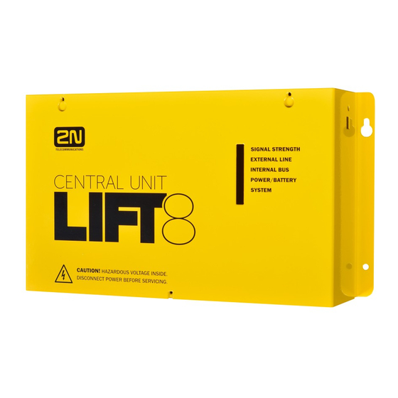
The audio units cannot be connected to a telephone line without the When shared by multiple shafts, the audio units cannot be connected without the and splitters. ® 918600 2N Lift8 Central Unit ® Figure: 2N Lift8 Central Unit For connection of up to 8 lifts to a GSM/UMTS/PSTN line. Including a power EURO cable and rechargeable battery. - Page 9 ® Figure: 2N Lift8 Splitter – lift audio unit interconnection. ® 918610E 2N Lift8 Audio Unit – Cabin Universal (Normal version) ® Figure: 2N Lift8 Audio Unit – Cabin Universal Audio unit electronics for lift cabin building in. Including speaker and microphone (HandsFree).
- Page 10 ® 918610EX 2N Lift8 Audio Unit – Cabin Universal – Cable Version Contains LED, microphone and speaker connected to cables. ® Figure: 2N Lift8 Audio Unit – Cabin Universal – Cable Version ® 918611E 2N Lift8 Audio Unit – Machine Room/Control Centre ®...
- Page 11 ® 918612E 2N Lift8 Audio Unit – Shaft ® Figure: 2N Lift8 Audio Unit – Shaft Audio unit for cabin roof and shaft or cabin bottom. Robust yellow cover. HandsFree mode, ALARM button and Triphony, LED indicators. Not intended for use in the cabin.
- Page 12 Audio Unit – Fireman Used for fire fighting operations. Activates top priority calls. ® 918610FZK 2N Lift8 Audio Unit – Fireman DPS (1 button) ® 918619E 2N Lift8 Audio Unit – Fireman DPS (knob + 1 push-to-talk button) ® TELEKOMUNIKACE a.s., www.2n.cz...
- Page 13 ® Figure: 2N Lift8 Audio Unit – Fireman DPS Used by fire fighting operations. Activates top priority calls. 918617E 2N® Audio Unit - Shaft Antivandal ® TELEKOMUNIKACE a.s., www.2n.cz...
- Page 14 918622 2N® Lift8 Camera Module Figure: 2N® Lift8 Camera Module For camera connection (IP, RS232, RS485) to the lift cabin. Every cabin in each shaft can contain a camera module (up to 8 camera modules in 2N® Lift8). ® TELEKOMUNIKACE a.s., www.2n.cz...
- Page 15 918XXX 2N® Lift8 RS232 Module Obrázek: 2N® Lift8 RS232 Module The RS232 module connects the 2N® Lift8 system with the lift control unit. The lift control unit transmits a command via RS232 to the Central Unit for processing and executing.
- Page 16 For Central Unit connection via a mobile network. Optional data connection for remote system configuration. ® 918651E 2N Lift8 UMTS Module ® Figure: 2N Lift8 UMTS Module For Central Unit connection via a mobile network. Optional data connection for remote system configuration.
- Page 17 ® 918652E 2N Lift8 PSTN Module ® Figure: 2N Lift8 PSTN Module For Central Unit connection via an analogue line. ® TELEKOMUNIKACE a.s., www.2n.cz...
- Page 18 ® 918653E 2N Lift8 VoIP Module ® Figure: 2N Lift8 VoIP Module For Central Unit connection via a VoIP line. ® TELEKOMUNIKACE a.s., www.2n.cz...
- Page 19 ® Cooperating 2N Applications ® 918700E 2N Lift8 Service Tool ® Figure: 2N Lift8 Service Tool ® Lift8 Service Tool application is intended for remote supervision and ® Lift8 configuration of the communicators. ® 918700E 2N Lift8 Control Panel ®...
- Page 20 ® 918700E 2N Lift8 Communicator ® Figure: 2N Lift8 Communicator ® Lift8 Communicator application is intended for receiving alarm calls by the dispatcher. ® 918700E 2N Lift8 Server ® Figure: 2N Lift8 Server ® TELEKOMUNIKACE a.s., www.2n.cz...
- Page 21 ® Lift8 Server application processes check calls and mediates communication between the s and PC applications. ® Associated 2N Products ® 918655E – 2N Lift8 External Pictograms Driver ® Figure: 2N Lift8 External Pictograms Driver ® Transforms the Lift8 cabin LED outputs into universal pilot lamps.
-
Page 22: Upgrade
P Improvements in applications Firmware 1.7.0 Camera module New protocols: CPC Antenna/KONE 2N ext. and P100 2N ext. (shaft 1.7.0 number and audio unit type identification) DE language support Auto-delete of archive records Firmware 1.8.0 1.8.0 Modified Groups menu in the Control Panel PT language support Firmware 1.9.0... -
Page 23: Terms And Symbols Used
Useful information for quick and efficient functionality. Note Routines or advice for efficient use of the device. Future Functions, New Features The grey-marked text in this document designates the functions and features that are under preparation or development at present. ® TELEKOMUNIKACE a.s., www.2n.cz... -
Page 24: Description And Installation
2.8 GSM/UMTS Module 2.9 VoIP Module 2.10 Audio Unit – Fireman 2.11 I/O Module 2.12 Camera Module 2.13 RS232 Module 2.14 Audio Unit – Shaft Antivandal Each subsection includes: Description of Components Before You Start Fitting Electrical Wiring ® TELEKOMUNIKACE a.s., www.2n.cz... -
Page 25: Pstn/Gsm/Umts/Voip Central Unit
2.1 PSTN/GSM/UMTS/VoIP Central Unit Description Figure: Central Unit ® TELEKOMUNIKACE a.s., www.2n.cz... - Page 26 Figure: Central Unit Indication Elements ® TELEKOMUNIKACE a.s., www.2n.cz...
- Page 27 Figure: Central Unit Connectors There are a USB connector and reset button to the right of the (see the figure below). Figure: USB Connector and Reset Button ® TELEKOMUNIKACE a.s., www.2n.cz...
- Page 28 Do not keep your PC connected for a long time unless necessary to reduce the computer damage due voltage surge from the telephone line during storms, for example. Warning Do not open the CU during the warranty period. Open the only to replace the rechargeable batteries after the warranty period. ® TELEKOMUNIKACE a.s., www.2n.cz...
- Page 29 On an easily accessible place there is a risk of telephone line misuse or SIM card misappropriation . is mounted on a wall with the included wall plugs and screws. ® TELEKOMUNIKACE a.s., www.2n.cz...
- Page 30 4. When removing the cover, proceed with caution, be careful about the earth wire connecting the cover with the bottom part. Do not disconnect the wire unless there is a reason to do so! 5. Interconnect the rechargeable batteries and connect them with the motherboard ® TELEKOMUNIKACE a.s., www.2n.cz...
- Page 31 1 h is guaranteed only if up to 20 audio units are connected in the system. The required 1h backup is not guaranteed if more than 20 audio units are installed. ® TELEKOMUNIKACE a.s., www.2n.cz...
- Page 32 Splitter – CU Bus Connection Interconnect the and splitter using a 6-wire main bus (power + - , audio + - , data + - ). Mind the polarity. ® TELEKOMUNIKACE a.s., www.2n.cz...
- Page 33 With a tow cable, consider the cable length too. With special cables (to the cabin), use the neighbouring wires and make sure that the nearest surrounding wires do not radiate interference (power wire, video signal etc.). ® TELEKOMUNIKACE a.s., www.2n.cz...
- Page 34 CU, splitter or I/O module. Caution Find the 2-pin termination resistance connector between the main bus connector and audio unit connectors (see the figure below). By default, the termination resistance is connected (jumper mounted). ® TELEKOMUNIKACE a.s., www.2n.cz...
- Page 35 Examples of Connection: ® TELEKOMUNIKACE a.s., www.2n.cz...
- Page 36 (so-called priority connection – electronic burglar alarm, e.g.). No dual or party lines may be used. No telephone “multiplugs” (adaptors), even the smart ones, may be used. ® Never connect Lift8 to an ISDN line. ® TELEKOMUNIKACE a.s., www.2n.cz...
- Page 37 Other recommendations ® Make an agreement with the PBX owner regarding operating costs (2N Lift8 outgoing calls are billed at the owner‘s expense with the exception of free calls via “green lines”).
- Page 38 PSTN line during the lift fitting time. In this case do not enable the lift blocking function until the telephone line is connected. VoIP VoIP is the cheapest solution where a reliable Internet connection is available. ® TELEKOMUNIKACE a.s., www.2n.cz...
-
Page 39: Splitter
The splitters are connected in series, i.e. one after another (never in parallel), to avoid system instability. The termination resistance (jumper) is mounted on the last splitter or IO module (furthest from the ® Figure: 2N Lift8 Splitter Caution Local power supply is not supported yet. ® TELEKOMUNIKACE a.s., www.2n.cz... - Page 40 Audio Unit s and Splitter Interconnect the splitter and a udio unit s using a two-wire bus maintaining polarity. Audio unit bus 1 … Bus for Audio Units + 2 … Bus for Audio Units - ® TELEKOMUNIKACE a.s., www.2n.cz...
- Page 41 The control electronics must ensure that, after the contact opening, the lifts in operation go down to the nearest station and the doors open. Caution This function may be mandatory depending on the regulations applicable for the given country and time of installation. ® TELEKOMUNIKACE a.s., www.2n.cz...
- Page 42 Connect the jumper to the first and last device (CU, splitter or I/O module) on the bus. Refer to the CU describing section for more details on termination resistance mounting. By default, the termination resistance jumper is off. Figure: Termination Resistance Off ® TELEKOMUNIKACE a.s., www.2n.cz...
- Page 43 Hang the device using the pre-drilled holes on the device bottom. Figure: Wall Mounting DIN Rail Mounting Mount the device on a standard TS 35 DIN rail. The recommended DIN rail length is 14 Figure: DIN Rail Mounting ® TELEKOMUNIKACE a.s., www.2n.cz...
- Page 44 A wrong mounting procedure may lead to damage to the electronics due to water infiltration. The splitter circuits are constantly under voltage and water leakage causes electrochemical reaction. No warranty can be claimed for products damaged in this manner! ® TELEKOMUNIKACE a.s., www.2n.cz...
-
Page 45: Audio Unit - Cabin Universal
The user does not come into a direct contact with this product. The control and indication elements depend on the specific installation. The functions of the indication elements correspond to the applicable standards Figure: Audio Unit – Cabin Universal ® TELEKOMUNIKACE a.s., www.2n.cz... - Page 46 4 terminals slid onto the board; see the photo 1 jumper slid onto the board; see the cover printing 1 mounting panel 1 speaker connected directly or by cable 1 microphone connected directly or by cable 1 cover with printing 5 tightening straps ® TELEKOMUNIKACE a.s., www.2n.cz...
- Page 47 Do not use this type of audio unit in a position other than mounted on a sufficiently large board. The acoustic properties of an uninstalled audio unit cannot be guaranteed. ® TELEKOMUNIKACE a.s., www.2n.cz...
- Page 48 May I place the speaker on the cabin ceiling? This placement is not recommended. May I use a longer cable to the speaker? For the speaker yes, but we do not recommend it for the microphone. ® TELEKOMUNIKACE a.s., www.2n.cz...
- Page 49 Two LED signal lamps (other side) Audio unit position 1. (yellow) Request received ALARM and CANCEL negation 2. (green) Connection confirmed Note If external LEDs are connected to connectors 7 and 8, LED indicators 1 and 2 will not be shining. ® TELEKOMUNIKACE a.s., www.2n.cz...
- Page 50 3 – under the cabin, 4 – shaft bottom). Configure the required changes as printed on the electronics cover. If you have removed the cover, put it back in the original position and tighten the screw. ® TELEKOMUNIKACE a.s., www.2n.cz...
- Page 51 The position-setting jumpers are employed exceptionally, e.g. where a certain audio unit type is used in a position other than normally intended. To recover the initial address setting, follow the drawing on the cover. ® TELEKOMUNIKACE a.s., www.2n.cz...
- Page 52 Pull the terminal out of connector 1 - Audio units bus, connect the bus audio units wires and replace the terminal to connector 1. Mind the polarity. Warning The audio unit is intended for 2N® Lift8 audio unit bus connection exclusively. Do not connect it to other wires to avoid its damage or destruction.
- Page 53 (6th pin on jumper 12) – CANCEL without jumper fitted (factory setting). If you use a break contact, fit the jumper (6th pin on jumper 12) – CANCEL inverted – jumper fitted. ® TELEKOMUNIKACE a.s., www.2n.cz...
- Page 54 LED requiring a current of approx. 5 mA (with diode loss of about 2 V), no power supply is needed. See the figure below for the connection. Figure: Alternative LED Connection for Audio Unit – Cabin Universal ® TELEKOMUNIKACE a.s., www.2n.cz...
- Page 55 AC and DC power supplies can be used for powering the lamps. To protect the Car Unit and Pictogram Driver against damage caused by shorts, always use the included isolating tube when installing the device! Wiring diagram ® TELEKOMUNIKACE a.s., www.2n.cz...
- Page 56 Lift8 External Pictogram Driver is in compliance with the essential requirements and other relevant provisions of the 1999/5/EC Directive. ® The Declaration of Conformity is attached to the basic module of 2N Lift8 and also available at www.2n.cz Volume Configuration Slightly loosen the four screws and shift the cover downwards.
- Page 57 Warning Remember to set the rescue password (parameter 992) to activate the rescue function. The rescue process can only be activated on a cabin audio unit configured as the cabin (default audio unit setting). ® TELEKOMUNIKACE a.s., www.2n.cz...
-
Page 58: Audio Unit - Machine Room
You can connect an external siren to the audio unit for incoming call signalling. You can configure the machine room audio unit to be shared by multiple lifts. ® TELEKOMUNIKACE a.s., www.2n.cz... - Page 59 Connect a handset supplied by the manufacturer to the audio unit to avoid handset operation error. Product Completeness Check Check the product for completeness before installation. 1 audio unit 2 wall plugs 2 wall plug screws 7–8 jumpers for common machine room configuration ® TELEKOMUNIKACE a.s., www.2n.cz...
- Page 60 Note Having set more addresses for the audio unit , press the TRIPHONY button to activate communication of the lift audio units with the lowest of the configured addresses. ® TELEKOMUNIKACE a.s., www.2n.cz...
- Page 61 Make sure that the polarity is maintained. Warning The audio unit is intended for 2N® Lift8 audio unit bus connection exclusively. Do not connect it to other wires to avoid its damage or destruction.
- Page 62 Caution Use the trimmer to set the best acoustic properties eliminating feedback. Volume configuration only works in the HandsFree mode. ® TELEKOMUNIKACE a.s., www.2n.cz...
-
Page 63: Audio Unit - Shaft
The audio unit contains a built-in microphone and a speaker. A handset can be connected for better acoustic properties. Thanks to its size and robustness, the audio unit has a very good, strong sound. ® TELEKOMUNIKACE a.s., www.2n.cz... - Page 64 Push the ALARM button, for example, when someone falls down the shaft. audio unit calls the numbers configured in the ALARM memory – set 2 (021–026). The ALARM button illumination (not required by default) helps you find and activate the audio unit easily in the dark ® TELEKOMUNIKACE a.s., www.2n.cz...
- Page 65 Electrical Installation Connectors audio unit has one connector for bus connection. The second RJ–11 connector is used for handset connection. Both the connectors are under the side doors. ® TELEKOMUNIKACE a.s., www.2n.cz...
- Page 66 Make sure that the polarity is maintained. Warning The audio unit is intended for 2N® Lift8 audio unit bus connection exclusively. Do not connect it to other wires to avoid its damage or destruction.
- Page 67 Volume Configuration Open the protective door on the audio unit and adjust the volume using the trimmer. Caution Use the trimmer to set the best acoustic properties eliminating feedback. Volume configuration only works in the HandsFree mode. ® TELEKOMUNIKACE a.s., www.2n.cz...
-
Page 68: Audio Unit - Compact
Figure: Description of Audio Unit – Cabin Compact Operation Push the ALARM button to activate the audio unit. The 'Establishing connection' symbol goes on. The 'Connection established' symbol goes on when communication is set up. ® TELEKOMUNIKACE a.s., www.2n.cz... - Page 69 Just drill holes into the cabin wall as shown in the figure below (also see the 1:1 figure on the product box). The larger hole is intended for cabling. Round the hole edges to avoid cable damage! ® TELEKOMUNIKACE a.s., www.2n.cz...
- Page 70 Do not complete the mounting procedure until connecting the device electrically (see below). Electrical Installation Caution Connect the wires before mounting the audio unit on the lift cabin wall. The connectors are separable – remove them, connect the wires, tighten the screws and replace the connectors. ® TELEKOMUNIKACE a.s., www.2n.cz...
- Page 71 (keep polarity as shown on the audio unit cover) and replace the connector. Warning The audio unit is intended for 2N® Lift8 audio unit bus connection exclusively. Do not connect it to other wires to avoid its damage or destruction.
- Page 72 Rotary Switch There is a glass-covered rotary switch on the audio unit front side. Use the switch to set ALARM/CANCEL (normal/inverted input) and audio unit type (cabin, cabin roof, cabin bottom, shaft bottom). ® TELEKOMUNIKACE a.s., www.2n.cz...
- Page 73 CANCEL Set the rotary switch (under the front glass) to position 2 to make ALARM be controlled by contact opening or voltage disconnection and CANCEL be controlled by contact closing or voltage connection. ® TELEKOMUNIKACE a.s., www.2n.cz...
- Page 74 The door opening signal must be active even during power outage. Note Make sure that delayed calling is configured to make the CANCEL input connection effective. ® TELEKOMUNIKACE a.s., www.2n.cz...
- Page 75 If you can access the cabin wall from the back side, follow the instructions in item a) or b). If not, obey the steps in item c). ® TELEKOMUNIKACE a.s., www.2n.cz...
- Page 76 Then push the set through the pre-drilled holes and insert the fan washers and nuts from the back. If you cannot access the cabin wall from the rear, follow the instructions on ® TELEKOMUNIKACE a.s., www.2n.cz...
- Page 77 Although not equipped with nuts, the screws will prevent the product from shifting or turning. Mounting Completion – Without Rear Access ® TELEKOMUNIKACE a.s., www.2n.cz...
- Page 78 Tighten slightly. Connection of induction loop for hearing-impaired The induction loop for people with impaired hearing is part of the Compact cabin audio unit. No more accessories are required for the given case. ® TELEKOMUNIKACE a.s., www.2n.cz...
-
Page 79: Pstn Module
6. Be careful while putting the module on the pins. Make sure that you have connected all the pins to the module connector. 7. Having fitted the pins into the connector correctly, you can fix the module using 2 bolts and 1 screw. ® TELEKOMUNIKACE a.s., www.2n.cz... - Page 80 8. Now connect the PSTN line. There are 2 options: using the RJ 11 connector; using a slide-on terminal board. Warning While fitting the module, make sure that all the pins are fitted correctly into the connector to avoid module damage. ® TELEKOMUNIKACE a.s., www.2n.cz...
-
Page 81: Gsm/Umts Module
7. While fitting the module mind the antenna connector. Make sure that it is pushed through the cover hole. 8. Having fitted the pins into the connector correctly, you can fix the module using 2 bolts and 1 screw ® TELEKOMUNIKACE a.s., www.2n.cz... - Page 82 Caution In places with a poor signal quality find an appropriate place or use a special (directional) antenna. Should you have DTMF transmission problems, set parameter 710 to 1 (for GSM modules only). ® TELEKOMUNIKACE a.s., www.2n.cz...
-
Page 83: Voip Module
6. Be careful while putting the module on the pins. Make sure that you have connected all the pins to the module connector. 7. Having fitted the pins into the connector correctly, you can fix the module using 2 bolts and 1 screw ® TELEKOMUNIKACE a.s., www.2n.cz... - Page 84 8. Now connect the VoIP line via the RJ–45 connector. Warning While fitting the module, make sure that all the pins are fitted correctly into the connector to avoid module damage. Caution In Lift8 is only supported codec A-Law ® TELEKOMUNIKACE a.s., www.2n.cz...
-
Page 85: Audio Unit - Fireman
2.10 Audio Unit – Fireman The Fireman audio unit is available in two versions. 2.10.1 Fireman PCB 2.10.2 Fireman 2.10.3 Fireman – Mechanical Mounting ® TELEKOMUNIKACE a.s., www.2n.cz... - Page 86 The Fireman call is set up by the cabin audio unit in one and the same shaft. You can join in the Fireman call from a machine room audio unit configured as the intercom. Button is not included. ® TELEKOMUNIKACE a.s., www.2n.cz...
- Page 87 2s) on the audio unit keypad (green LED shining) to join in the call. Push (for longer than 2 s) on the audio unit keypad (green LED flashing) to leave the call without terminating it. ® TELEKOMUNIKACE a.s., www.2n.cz...
- Page 88 1 speaker (directly or cable connected) 1 microphone (directly or cable connected) 1 printed cover Mounting Electronic Installation This audio unit is designed for mounting behind the lift control panel. Prepare the panel for installation as shown below: ® TELEKOMUNIKACE a.s., www.2n.cz...
- Page 89 Leave no gap between the lift control panel and the audio unit surface to avoid acoustic speaker fault and acoustic speaker-microphone feedback. Do not use this type of audio unit otherwise than mounted on a sufficiently large board. The acoustic properties of an uninstalled audio unit cannot be guaranteed. ® TELEKOMUNIKACE a.s., www.2n.cz...
- Page 90 Yes, but keep the impedance of 64 Ω. Doing this, however, you assume responsibility for sufficient volume and frequency range. Can I use a longer cable for the speaker? You can use a longer cable for the speaker, but not for the microphone. ® TELEKOMUNIKACE a.s., www.2n.cz...
- Page 91 Electric Installation Description of Terminals, Connectors and Jumpers Figure: Terminals, Connectors and Jumpers on Cabin Audio Unit – Universal Board ® TELEKOMUNIKACE a.s., www.2n.cz...
- Page 92 Pull the terminal out of connector 1 – Audio units bus, connect the bus audio units wires and replace the terminal to connector 1. Mind the polarity. Warning The audio unit is intended for 2N® Lift8 audio unit bus connection exclusively. Do not connect it to other wires to avoid its damage or destruction.
- Page 93 Loosen the four screws slightly and move the cover downwards. Remove the cover. Use the trimmer in the lower part of the electronics to adjust the volume (see the figure below). Caution Use the trimmer to set the best acoustic properties while eliminating feedback. ® TELEKOMUNIKACE a.s., www.2n.cz...
- Page 94 If the control-centre (intercom) configured machine room audio unit is used, the Fireman call is signalled by a green LED flashing on the audio unit. Push (for longer than 2 s) on the audio unit keypad (green LED shining) to join in the call. Push ® TELEKOMUNIKACE a.s., www.2n.cz...
- Page 95 Fireman audio unit and the cabin and machine room audio units in one and the same lift shaft. If any of the machine room audio units is configured as the control centre (intercom), you can join in the Fireman call. ® TELEKOMUNIKACE a.s., www.2n.cz...
- Page 96 If the control-room (intercom) configured machine room audio unit is used, the Fireman call is signalled by a green LED flashing on the audio unit. Push (for ® TELEKOMUNIKACE a.s., www.2n.cz...
- Page 97 You can join in the Fireman call from a machine room audio unit configured as the intercom. Before You Start Product Completeness Check ® Please check the Lift8 Fireman package for completeness before starting installation: ® 1 2N Lift8 Fireman 1 double Torx 10 / Torx 20 ®...
- Page 98 Detent button (knob) connector Volume setting (trimmer) Configuration jumper Button connector (Push to talk) Servicing connector Bus Connection Remove the audio unit cover and unplug terminal 2 (audio unit bus). Connect the bus and replace the terminal keeping polarity. ® TELEKOMUNIKACE a.s., www.2n.cz...
- Page 99 Warning The audio unit is intended for 2N® Lift8 audio unit bus connection exclusively. Do not connect it to other wires to avoid its damage or destruction. Keep polarity while connecting the audio unit to make the audio unit work properly.
- Page 100 See below for an overview of mounting types and list of necessary components. Wall Mounting For concrete and steel structures, etc. What you need for installation: ® Lift8 Fireman only (no need for covering frame) Flush Mounting – Classic Bricks What you need for installation Properly cut-out hole or, optionally, a flush mounting kit, Part No.
- Page 101 Flush Mounting – Thermally Insulated Wall What you need for installation Longer screws (depending on the thermal insulation thickness) ® Lift8 Fireman Covering frame: contact your distributor Flush Mounting – Hollow Bricks What you need for installation Flush mounting kit, Part No. 9151001 ®...
- Page 102 90 mm. Do not use lower-quality plugs to avoid their pulling out of the wall! ® Lift8 Fireman is assembled with stainless steel screws. Using different, lower-quality screws may lead to screw and surface corrosion! Make sure that no impurities get into the device (especially on the sealing and microphone sound guides) after removing the front panel.
- Page 103 Flush Mounting – Classic Bricks Follow the instructions for the flush mounting kit if used. Follow the instructions below if you do not use the flush mounting kit. ® TELEKOMUNIKACE a.s., www.2n.cz...
- Page 104 90 mm. It is assumed that all the necessary cables lead to the predrilled hole. Now follow the instructions for classic brick mounting yet respect a lower strength of thermally insulated walls while tightening the screws. ® TELEKOMUNIKACE a.s., www.2n.cz...
- Page 105 Flush Mounting – Hollow Bricks It is practically impossible to fit plugs into hollow bricks because the inner brick walls are too thin for drilling. Therefore, use the flush mounting kit and follow the instructions included therein. ® TELEKOMUNIKACE a.s., www.2n.cz...
- Page 106 Flush Mounting – Plasterboard Use the flush mounting kit for plasterboard walls and follow the instructions included therein. ® TELEKOMUNIKACE a.s., www.2n.cz...
-
Page 107: I/O Module
The I/O Modules are connected serially (in line). Do not use parallel connection to avoid system instability. Connect the termination resistance connecting jumper to the last device (Splitter or I/O Module furthest from the CU). See the figures below for terminal layout details. Figure: I/O Module – Lower Side ® TELEKOMUNIKACE a.s., www.2n.cz... - Page 108 (power + -, audio + -, data + - ) – see the I/O Module cover. Connect the devices serially (in line). Parallel connection is not allowed. Refer to the CU section for more details. ® TELEKOMUNIKACE a.s., www.2n.cz...
- Page 109 Use a 10-pin rotary switch 0–9 (see the figure above) to set the I/O Module address for a lift. Set 1–8 like the shaft number for the splitter (set 5 for lift 5, e.g.). Warning Do not set address 0 and 9 to avoid system error. ® TELEKOMUNIKACE a.s., www.2n.cz...
- Page 110 At the same time, every status change is recorded in the system log for later use and the user is informed via a pop-up window. See the figure below for an example of input circuit connection. Figure: Example of Input Circuit Connection ® TELEKOMUNIKACE a.s., www.2n.cz...
- Page 111 See below for the mounting types and necessary components. Install the device on sites not exposed to water leakage or condensation. Wall Mounting Use appropriate wall plugs and screws for mounting (not included in the delivery). Hang the device using the pre-drilled holes on the device bottom. ® TELEKOMUNIKACE a.s., www.2n.cz...
- Page 112 A wrong mounting procedure may lead to damage to the electronics due to water infiltration. The splitter circuits are constantly under voltage and water leakage causes electrochemical reaction. No warranty can be claimed for products damaged in this manner! ® TELEKOMUNIKACE a.s., www.2n.cz...
-
Page 113: Camera Module
RS-485 type. The camera module can work with the Central Unit (CU), or autonomously. It contains a microSD card slot for recording images in variable intervals. Connect the camera module to the CU or splitter via a 2-wire bus to support the 2N® Lift8 communication. - Page 114 Connect the camera module to the LAN if the IP camera is installed in the LAN. If the camera module is connected to the Lift8 system, use the Service Tool for configuration (refer to Subs. 5.3 - Service Tool - Use for more details).
- Page 115 Direct IP camera - camera module connection ® TELEKOMUNIKACE a.s., www.2n.cz...
- Page 116 Retrieve IP address from DHCP server option is enabled for the camera. Switch on the local power supply. RS-232/RS-485 Camera Connection Set only the resolution, compression, snapshot interval and Record limit/file parameters for the RS232 and RS485 cameras. ® TELEKOMUNIKACE a.s., www.2n.cz...
- Page 117 Caution The RS232 and RS485 cameras work without a local power supply too in the Lift8 system only if they have a low current consumption. Saving files to an SD card does not work without a local power supply. We recommend you to switch on a local power supply because cameras usually take more current in the night mode (for infrared illumination).
- Page 118 Caution The OK LED is flashing and ERR LED is illuminated when the unit is being upgraded. Caution Use the 2N® Lift8 Service Tool application to set the camera type and other parameters. Camera Module Setting Set the 2N® Lift8 camera module via the 2N®...
- Page 119 DHCP server option is enabled for the camera. Refer to network.cfg for more setting details. Having set the network parameters, you can open the Internet browser to go on configuring via the web interface (see the Web Interface below). ® TELEKOMUNIKACE a.s., www.2n.cz...
- Page 120 Refer to camera.cfg for more setting details. Date and Time Settings (time.cfg) Default Parameter name Note value Set the time zone in which the camera module Coordinated Universal is located. Time Date ( dd:mm:yyyy 01.01.1970 Time ( hh:mm:ss 00:00:00 ® TELEKOMUNIKACE a.s., www.2n.cz...
- Page 121 The user name is always Admin (not respecting the upper/lower case). Standalone Camera Module Upgrade Refer to 2N® Lift8 Camera Module at www.2n.cz for the latest firmware (ln_app_camera.bin). Download the file to a microSD root directory. When you insert the microSD card, the file (ln_app_camera.bin) will be loaded onto the dataflash (yellow LEDs flashing) and then the module will get restarted.
- Page 122 ® TELEKOMUNIKACE a.s., www.2n.cz...
- Page 123 SD card and load the files directly from the card to get the files more quickly. Relay Control HTTP Commands You can also use http commands to close/open the relay. ® TELEKOMUNIKACE a.s., www.2n.cz...
- Page 124 Use appropriate wall plugs and screws for mounting (not included in the delivery). Hang the device using the pre-drilled holes on the device bottom. Obrázek: Wall Mounting DIN Rail Mounting Mount the device on a standard TS 35 DIN rail. The recommended DIN rail length is 14 ® TELEKOMUNIKACE a.s., www.2n.cz...
- Page 125 A wrong mounting procedure may lead to damage to the electronics due to water infiltration. The Camera Module circuits are under constant voltage and water leakage causes electrochemical reaction. No warranty can be claimed for products damaged in this manner! ® TELEKOMUNIKACE a.s., www.2n.cz...
-
Page 126: Rs232 Module
Product Completeness Check Check whether the product package is complete before installation. The RS232 module package contains: 1 electronics board (RS232 module) 2 long threaded spacers, 1 short screwed spacer 1 screw RS232 cable cable bushing ® TELEKOMUNIKACE a.s., www.2n.cz... - Page 127 To make your spacer mounting easier, turn the screw until it stops and use a cross-point screwdriver to fit the spacer. Having tightened the spacer in the LED plastic cover, use flat-nose pliers to secure the spacer against spinning and remove the screw. ® TELEKOMUNIKACE a.s., www.2n.cz...
- Page 128 Now mount the RS232 module. Be careful while putting the module on the pins. Make sure that you have connected all the pins to the module connector. Having fitted the pins into the connector correctly, you can fix the module using 3 screws (see Fig.). ® TELEKOMUNIKACE a.s., www.2n.cz...
- Page 129 Send SMS AT+CMGS=603123456,145<CR>sms 129 - national text<Ctrl+z> number Select AT+CMGF= AT+CMGF=1 mode Return edited Enable ATE1 ATE1 characters to the echo terminal Disable ATE0 ATE0 echo See ATE0 Start command here for details on AT commands. ® TELEKOMUNIKACE a.s., www.2n.cz...
- Page 130 GSM/UMTS module for sending SMS. Serial Port Configuration You can only set the transmission rate of 9600-115200 bauds for the serial port. The other parameters are preset: Bits per word 8 bits Parity no parity Stop bits 1 stop bit ® TELEKOMUNIKACE a.s., www.2n.cz...
-
Page 131: Audio Unit - Shaft Antivandal
This unit is designed for outdoor applications too. Press the ALARM button to establish connection with the control centre. The audio unit is equipped with an integrated microphone and speaker and, thanks to its dimensions and strength, provides a good and strong sound. ® TELEKOMUNIKACE a.s., www.2n.cz... - Page 132 The ALARM button is not illuminated at relax. Before You Start Product Completeness Check Check the product package for completeness before installation: 1 2N® Lift8 Shaft Antivandal 1 Torx 10 / Torx 20 double-ended spanner Bushings (extra package): 1 2N® Lift8 Shaft Antivandal...
- Page 133 Desription of Terminals, Connectors and Jumpers Figure: Audio Unit - Fireman Terminals, Connectors and Jumpers Terminals and Connectors speaker connector 2 microphone connectors audio unit bus lockable button connector (knob) volume control configuration jumper button connector (push to talk) servicing connector ® TELEKOMUNIKACE a.s., www.2n.cz...
- Page 134 Maintain polarity (see the Audio Unit - Fireman Terminals, Connectors and Jumpers figure above). Warning The audio unit is intended for 2N® Lift8 audio unit bus connection exclusively. Do not connect it to other wires to avoid its damage or destruction.
- Page 135 An improper mounting may result in the audio unit not being waterproof. Water leakage may damage the electronics. 2N® Lift8 Shaft Antivandal is assembled with stainless steel screws. If you lose them, never use other screws to avoid corrosion and screw appearance deterioration! ®...
-
Page 136: System Configuration
3. System Configuration The system is supplied pre-configured. ® This section describes the Lift8 configuration. There are three ways how to progr ® am 2N Lift8 3.1 Lift8 Programming 3.2 Table of Parameters (FW 1.10.0) 3.3 SMS Configuration ® TELEKOMUNIKACE a.s., www.2n.cz... -
Page 137: Lift8 Programming
3.1 Lift8 Programming ® The advantage of the Lift8 (hereinafter referred to as ) system is that it is programmed via the where all the parameters are stored. Hence, you do not have to reconfigure anything to replace an Audio Unit and you can program just one multiple lift systems, for example. - Page 138 Audio Unit in the standby mode. If you only want to go one menu back, press If you are not quite sure of how will behave after programming, save the filled-in form for later check. ® TELEKOMUNIKACE a.s., www.2n.cz...
- Page 139 In such cases, try some other equipment (a digital PBX, e.g.) or the machine room telephone set. If the machine room or PSTN programming attempts fail too, you have probably entered an invalid password. Programming via Service Tool ® Refer to the Service Tool section (Section 5) for details. ® TELEKOMUNIKACE a.s., www.2n.cz...
- Page 140 ® TELEKOMUNIKACE a.s., www.2n.cz...
-
Page 141: Table Of Parameters (Fw 1.10.0)
Set 1 – ALARM up to 16 1-second pause while button memory empty programming is possible digits: 0–9 ® via a PC (use 2N Set 1 – ALARM up to 16 Service Tool button memory empty digits: 0–9 Set 1 – ALARM... - Page 142 CPC Antenna, 4= CPC KONE, 5 = P100, 6 = autodetection DTMF protocol (CPC Antenna/P100), 7 = CPC Antenna 2N ext, 8 = CPC KONE 2N ext, 9 = P100 2N ext 2N ext is a protocol that Set 1 –...
- Page 143 1-second pause while up to 16 Check call programming is possible empty memory 3 ® digits: 0–9 via a PC (use 2N Service Tool up to 16 Check call empty memory 4 digits: 0–9 up to 16 If the set of checking call...
- Page 144 16 Error call 1-second pause while empty programming is possible memory 4 digits: 0–9 ® via a PC (use 2N up to 16 Service Tool Error call empty memory 5 digits: 0–9 up to 16 Error call...
- Page 145 6 1= output on Default output state of IO ABCD empty Example: 1001= outputs module 7 1 and 4 will be on after Default output the system start. state of IO ABCD empty module 8 ® TELEKOMUNIKACE a.s., www.2n.cz...
- Page 146 0 = do not perform dial tone detection. A call is set up with any line tone. Enable dial 0–1 1 = perform dial tone tone detection detection. No call is set up if the dial tone is not detected. ® TELEKOMUNIKACE a.s., www.2n.cz...
- Page 147 ERROR in 6 minutes and the lift will be blocked in another 5 minutes). If the dialtone is detected again, Lift8 will pass into the "Line OK" state. The tone must be longer Min. dialtone 200–2000 ms...
- Page 148 0 = user recorded, 1 = voice menu language Language for User-recorded digits are numeric 0–1 played only if values 11, messages 12 or 13 are set in parameters 975–979 or 971. ® TELEKOMUNIKACE a.s., www.2n.cz...
- Page 149 Cautions: sequence by announcements in pressing 3 after sequence User messages call re recorded into the CU confirmation ® with the aid of the 2N up to 10 Service Tool Call end announcements in sequence sequence ® TELEKOMUNIKACE a.s., www.2n.cz...
- Page 150 16 digits: Set the rescue empty password 0–9 terminating password. 0 = disabled 1 = An audio test of Enable audio 0–1 selected audio units is unit self-test carried out after a check call. ® TELEKOMUNIKACE a.s., www.2n.cz...
- Page 151 Default 1103 communication outside gateway the internal net is made. Set the DNS server IP 1104 DNS server address. ** Set the IP address for connection to the 1105 SIP server counterparty (PBX, operator). ** ® TELEKOMUNIKACE a.s., www.2n.cz...
- Page 152 (is assigned expires by the opponent) Set the time zone (UTC) 1150 Time zone -12–12 in which 2N® Lift8 installed. Define how often 2N® Synchronisation 1151 60–86400 3600 Lift8 shall synchronise period with the SNTP server. ** Enable SNTP synchronisation.
- Page 153 * This parameter can only be configured via the voice menu (incoming call to 2N® Lift8 or via the machine roo m audio unit). ® ** This parameter can only be configured via the Service Tool Caution Parameters 1003 and 1004 are used for username and password configuration for verification at the provider's.
-
Page 154: Sms Configuration
(918653E 2N® Lift8 VoIP Module) modules! Caution Every SMS must meet the conditions listed below to be sent to 2N® Lift8 successfully. If not, the SMS will be ignored, no changes will be made and an error message will be sent to the SMS sending number. - Page 155 SMS-based configuration obeys the same rules and limitations as configuration via an application or a phone (maximum length, value range, two-digit limitation, etc.). If any of these rules is not met, 2N® Lift8 shall not set the parameters and shall send an error SMS specifying the wrong parameter.
- Page 156 If everything is OK, you will receive the following confirmation SMS: L8 RST OK Error Replies Should there be an error in the configuration SMS or command processing procedures, 2N® Lift8 transmits an error reply notifying that the command has not been executed! 2N® Lift8 sends error replies until all the configuration SMS parameters are correct and the command can be executed.
-
Page 157: Function And Use
Here is what you can find in this section: 4.1 User Instructions 4.2 Control Centre Instructions 4.3 Function Description (for Advanced Users) 4.4 Call Confirmation Types 4.5 Lift Blocking Function 4.6 Four-Lift Version 4.7 Intercom Function 4.8 System Completeness Check ® TELEKOMUNIKACE a.s., www.2n.cz... -
Page 158: User Instructions
. You can use the HandsFree mode or connect a handset to achieve better acoustic properties. Having entered the voice menu, you can select the following functions using the audio unit keypad. ® TELEKOMUNIKACE a.s., www.2n.cz... - Page 159 To listen to info about this communicator press 3 For IO modules press 4 To return to the main menu press # To end the call press # Note selection serves primarily for the configuration – refer to the Configuration section. ® TELEKOMUNIKACE a.s., www.2n.cz...
-
Page 160: Control Centre Instructions
Press 0 for connection with the last-calling audio unit , Enter the lift number X for connection with another audio unit , Press 9 for administration, information or rescue process, and Press # to end the call. ® TELEKOMUNIKACE a.s., www.2n.cz... - Page 161 This is due to the essential principle of the telephone line function where DTMF signalling is mixed with the call and thus may be masked by certain speech tones or noise. This, however, is not a defect of the product. ® TELEKOMUNIKACE a.s., www.2n.cz...
-
Page 162: Function Description (For Advanced Users)
Press the TRIPHONY button to enter the machine room voice menu get through to the other audio unit s of the same lift and set up triphony with the other shafts. ® TELEKOMUNIKACE a.s., www.2n.cz... - Page 163 A check call can be sent to the control centre via PSTN, GSM, UMTS or VoIP. Set the values in parameters 071–076 and 981 (refer to Subs. 3.2, Table of Parameters). ® TELEKOMUNIKACE a.s., www.2n.cz...
- Page 164 Press 0 in the voice menu for connection with the last-calling audio unit Incoming Call Voice Menu Welcome, this is a 2N Lift 8 communicator Press 0 to dial the last-calling audio unit Enter the lift number X to dial another audio unit...
- Page 165 ® A control centre with a PC workplace with the Lift8 server receives calls ® automatically as configured. Configure the server using the Lift8 Control Panel Overview of Announcements Announcement Meaning of announcement (English) Caution, the call is Approaching call end announcement.
-
Page 166: Call Confirmation Types
("Connection confirmed") and mutes the currently played announcement. The call goes on for the maximum DTMF char call time as configured. These digits are interpreted as control characters (refer to Subs. , Tone Dialling Control during Call). ® TELEKOMUNIKACE a.s., www.2n.cz... - Page 167 Used wherever the counterparty is equipped with the required SW. When the line is answered, a DTMF string is sent and the lift is identified. The call is either switched to voice communication (alarm call) or confirmed automatically and terminated (check call), as the case may be. ® TELEKOMUNIKACE a.s., www.2n.cz...
- Page 168 If such troubles occur, we recommend you to change the CPC/P100 (3/4) settings. 7,8,9. CPC (Antenna and KONE), P100 2N ext (for Alarm Calls only) The protocols work identically like for CPC (items 3 and 4) and P100 (item 5). The only difference is that they transmit shaft numbers and audio unit types too.
-
Page 169: Lift Blocking Function
1 minute at least (PSTN, VoIP). a power supply is connected to recharge the battery. Caution This function may be mandatory if the applicable regulations valid for the country and time of installation require so. ® TELEKOMUNIKACE a.s., www.2n.cz... -
Page 170: Four-Lift Version
Normal 8-Lift Connection If you set parameter 994 to 0, you can connect up to 8 lift shafts and up to 5 audio unit s to each shaft (machine room, cabin roof, cabin, cabin bottom, shaft bottom). ® TELEKOMUNIKACE a.s., www.2n.cz... - Page 171 Figure: 8-Lift Configuration ® TELEKOMUNIKACE a.s., www.2n.cz...
- Page 172 ® TELEKOMUNIKACE a.s., www.2n.cz...
-
Page 173: Intercom Function
For example, 011 – #8 means that a call to the machine room audio unit in the shaft of lift 8 is set in ALARM button memory 1. Setting options: Service Tool – enter # and the shaft number into parameters 011–016. ® TELEKOMUNIKACE a.s., www.2n.cz... - Page 174 PSTN, GSM, UMTS and VoIP networks (depending on the module used). To set up a check call to a machine room audio unit , you can set the number as described in the Alarm – Intercom subsection above. ® TELEKOMUNIKACE a.s., www.2n.cz...
-
Page 175: System Completeness Check
Use the RESET button again to make the system monitor all the audio units added later to the system. ® Such audio units are displayed in the Supervision - Added units menu in the 2N Service Tool ® Figure:... - Page 176 Disconnect all the audio units (mainly cabin and Fireman) by disconnecting the main bus and audio unit bus on the CU. It takes CU some time (several tens of seconds) to find out that all the units have been disconnected. Therefore, use the 2N® Service Tool to check whether all the units have logged out.
-
Page 177: Service Tool
5.1 Installation and Login 5.2 Introduction to Application 5.3 Use ® Refer to the Lift8 product pages at www.2n.cz , download section, fo r the latest FW version . You can use this link rom the online manual. ® TELEKOMUNIKACE a.s., www.2n.cz... -
Page 178: Installation And Login
Then you will also be asked whether the configuration files should be removed and the whole application with a new, empty database should be installed. ® Now the Lift8 Service Tool Setup Wizard has been launched. Follow the wizard ® instructions. Select the Lift8 Service Tool... - Page 179 Refer to the text below for the default values. Now connect the and click ® Connect. The Lift8 Service Tool automatically finds the connected on the PC and starts downloading parameters and logs. Having completing the download, the 2N ® Lift8 Service Tool is ready for work. ® TELEKOMUNIKACE a.s., www.2n.cz...
- Page 180 Click the option to find the driver in the PC. ® Click the option to select a driver from a list and select a 2N Lift8 model instead of Complex USB device.Now the driver starts working and, whenever you connect the Central Unit to the same PC USB port, the device will be detected correctly.
-
Page 181: Introduction To Application
The third menu level, if meaningful, gets displayed horizontally in the right-hand upper corner and includes a list of parameter setting forms. ® Figure: 2N Lift8 Service Tool Window The main menu contains three pop-up menus. The Device menu helps you connect to or disconnect from the . - Page 182 Age defines the maximum battery life and the age counter has to be reset whenever new batteries are inserted. When the battery life is exhausted, the CU reports an error and the batteries have to be changed. This helps ® TELEKOMUNIKACE a.s., www.2n.cz...
- Page 183 The lower part of the application includes the Logout button (to the right) and other important controls, which may be different in different menus. The table below describes all the buttons available in the application. ® TELEKOMUNIKACE a.s., www.2n.cz...
- Page 184 Connect to device screen. Back is only available in the Connect to device menu and helps you return to the Configuration / Parameters menu if you do not want to get connected to any ® TELEKOMUNIKACE a.s., www.2n.cz...
- Page 185 Get new image helps you download a preview from the camera connected to the selected camera module. Rotation to left turns the image left by 90°. Rotation to right turns the image right by 90°. ® TELEKOMUNIKACE a.s., www.2n.cz...
- Page 186 From device helps you download user messages from the To device helps you upload new user messages into the CU memory. Load from directory helps you load the list of user messages from a directory to a disk. ® TELEKOMUNIKACE a.s., www.2n.cz...
- Page 187 Save to directory saves the list of user messages into a selected folder onto a disk. Print HW setup - diagram helps you print out the current 2N® Lift8 HW settings as an image. ® Print HW setup - text...
- Page 188 Open from file and save to device opens a file viewer for you to select the licence file for your This file will be downloaded to the upon confirmation. ® TELEKOMUNIKACE a.s., www.2n.cz...
-
Page 189: Use
Maximum and Minimum define the permitted range of the values to be set. Default value displays the factory value of the parameter (which also appears after the factory reset). Click this value to add it to the value column. ® TELEKOMUNIKACE a.s., www.2n.cz... - Page 190 Click the funnel symbol in the selected column to activate the filter. Activation is indicated by a colour change of the funnel symbol; see the figure below. ® TELEKOMUNIKACE a.s., www.2n.cz...
- Page 191 A grey icon and greyish 'Not connected' description indicate an unconnected camera module. A yellow-highlighted icon plus a green 'Connected' text indicate that the camera module is connected to the CU and the camera is online. See the figure below. ® TELEKOMUNIKACE a.s., www.2n.cz...
- Page 192 Define the maximum size of the .mjpg file in hours in the Record limit/file parameter for memory card saving. The IP camera configuration section also includes DHCP settings camera module configuration. Refer to Subs. 2.12. for more setting and function details. ® TELEKOMUNIKACE a.s., www.2n.cz...
- Page 193 Figure: IP Camera Configuration Figure: RS232 Camera Configuration Press OK to confirm the settings and add the values to the table. Click Save to device to store the data in the memory and use it in the CU. ® TELEKOMUNIKACE a.s., www.2n.cz...
- Page 194 The other two buttons help turn the image left or right to optimise the view if the camera scans under the angle of 90°, for example. Close the window to quit the preview. Figure: Camera Window ® TELEKOMUNIKACE a.s., www.2n.cz...
- Page 195 Set the outputs similarly: enter the function name (Ventilator 4, e.g.), set the output relay negation in the Activation mode and specify the output colours for the Surveillance menu. ® TELEKOMUNIKACE a.s., www.2n.cz...
- Page 196 If you keep the default value 0 in the Duration parameter, the relay will keep closed/open during the input activation time. Example: if input 1 keeps 10 s at logic 1, the associated relay 1 will keep closed for 10 s too. ® TELEKOMUNIKACE a.s., www.2n.cz...
- Page 197 This solution is useful for installations where identical parameters are defined and can be simply copied to multiple central units. The LUA open-source programming language is used for the script. Refer to www.lua.org for more details. ® TELEKOMUNIKACE a.s., www.2n.cz...
- Page 198 Get module input state input state Checking module input m=module_pos i=input_addr return io_changed(m,i) was changed true if input changed Checking module is io_ready(m) m=module_pos ready send_sms(p,s) Send SMS p=phone_num s=sms text ® TELEKOMUNIKACE a.s., www.2n.cz...
- Page 199 Advanced settings to enable/disable message types and assign colours for easier log displaying and other advanced options. See below for details. The logs should only be analysed by duly trained persons or your Technical Support department. ® TELEKOMUNIKACE a.s., www.2n.cz...
- Page 200 This menu has been introduced specifically for monitoring all communication along the bus between the bus-connected devices and the Central Unit. Each row symbolises one device connected. The table columns specify the device, bus, address (for later search in the Logs menu) and communication parameters. ® TELEKOMUNIKACE a.s., www.2n.cz...
- Page 201 Count of requests received E_txreq Count of incorrectly sent requests E_txretry Count of incorrectly received requests E_drop_req Count of discarded requests (duplicate requests) E_drop_resp Count of discarded replies (duplicate replies) E_drop_ack Count of discarded reply confirmations (duplicate confirmations) ® TELEKOMUNIKACE a.s., www.2n.cz...
- Page 202 Player The Player menu helps save records of the cameras connected to the 2N® Lift8 camer a modules onto SD cards inserted in the camera modules. You have three options how to play a video record. The simplest is to remove the SD card from the camera module respecting the SD card connection/disconnection rules described in Subs.
- Page 203 User Messages User Messages helps you replace the default system announcements with user ® messages. Load these messages from a file or, in the correct format, via the 2N Lift8 Service Tool. Use the microphone connected to your PC to record the messages.
- Page 204 In case the application gain setting is not sufficient, use the system controllers or an external amplifier. When the maximum message time (8 minutes) is exhausted, no more messages can be added. Thus, optimise the message time to record all of your messages. ® TELEKOMUNIKACE a.s., www.2n.cz...
- Page 205 Enter the existing password into the Current password and the new password into the New password. Click Save password to device to confirm and save the new setting. Note ® Remember to change the password in the 2N Lift8 Service Tool configuration too for future connections.
- Page 206 . Enter a greater portion of the IMSI code to specify the SIM cards to be used in ® one network. You can add up to 10 IMSI codes to the licence. Contact your 2N Lift8 supplier or the manufacturer's Technical Support department ( sales@2n.cz...
- Page 207 Connected units menu provides a graphic diagram of all the units connected to 2N® Lift8. The following controls are available: Refresh to update the display, Press HW setting (diagram/text) to print out the diagram/text of all the Audio Units and splitters connected to the given CU.
- Page 208 Furthermore, states of all the inputs and outputs are included. The inputs and outputs are set to 0 by default upon the system startup. Logic 0 is on the input and the relay is open. Use the settings in the Configuration / IO Modules menu to change the relay ® TELEKOMUNIKACE a.s., www.2n.cz...
- Page 209 Configuration / IO Modules menu to add a brief description to an input/output. You can also select the active/inactive input/output state colour in the same menu to simplify the visual state identification. The logic state of the given object (input/output) is signalled with digits 0/1 in a colour ring. ® TELEKOMUNIKACE a.s., www.2n.cz...
-
Page 210: Server
Here is what you can find in this section: 6.1 Installation and Licensing 6.2 Use ® Refer to the Lift8 product pages at www.2n.cz, download section, for the latest FW version. You can use this link from the online manual. ® TELEKOMUNIKACE a.s., www.2n.cz... -
Page 211: Installation And Licensing
Make sure that the port is accessible from the LAN (see the Note above) ® and correctly set in all the applications. Now the wizard is ready to install your 2N Lift8 Server . It displays an overview of the settings. Check them carefully as you will not be able to modify them after installation unless you re-install the application! If you detect an error, press Back to return to the error window. - Page 212 Minimum operating system requirements: Windows Vista, 7, 8 Licensing ® All the Lift8 Server functions are subject to licence. Upon your first PC installation of the application, you will get a trial licence for 800-hour operation and 50-user and 50-lift (CU) connection.
- Page 213 ® Having received the licence file, start the Lift8 Licence Tool and enter the path to this file into the Licence path parameter. Click Upload to add the licence to the server directory and restart the server to update the licence data. The licence status will change into OK.
-
Page 214: Use
The database also includes a list of authorised users, which, depending on their user roles, can connect to the server, change configuration settings ® ® and/or process incoming alarm calls via the Lift8 Control Panel Lift8 Communicator ® Lift8 Server integrates a SIP station which can be assigned up to 8 independent accounts and process up to 32 parallel calls. - Page 215 Database import may only be executed when the server is stopped. If the server is running, the program identifies any importing attempt as an error. Enter the following command to stop the server: C:\Program Files\2N TELEKOMUNIKACE\ 2N Lift8\Server\l8-config.exe –cStopServer ® TELEKOMUNIKACE a.s., www.2n.cz...
- Page 216 If the database includes a high number of users and terminals, the table import will take a few minutes. Restart the server after every successful database import using the following command: C:\Program Files\2N TELEKOMUNIKACE\ 2N Lift8\Server\l8-config.exe –cStartServer Setting Options The l8-config program provides numerous server settings; see the long list below. parameters...
- Page 217 –sMaxLift sets the maximum count of lifts to be connected to the server at the same time. The maximum count is based on the licence. –sResetAdmin resets the Admin password to default '2n'. Server Commands –cStartServer starts the l8 server.
-
Page 218: Control Panel
Here is what you can find in this section: 7.1 Installation and Login 7.2 Introduction to Application 7.3 Use ® Refer to the Lift8 product pages at www.2n.cz, download section, for the latest FW version. You can use this link from the online manual. ® TELEKOMUNIKACE a.s., www.2n.cz... -
Page 219: Installation And Login
Then you will also be asked whether the configuration files should be removed or the whole application with a new, empty database should be installed. ® Now the Lift8 Control Panel Setup Wizard has been launched. Follow the ® wizard instructions. Select the Lift8 Control Panel... - Page 220 This connection cannot be removed. If you use one and the same PC for ® your Lift8 Control Panel and server, you can make use of these pre-settings ® and click the Connect icon. The Lift8 Control Panel will log in to the local server.
- Page 221 Caution Important! A default user with administrator login is created during the ® Lift8 Server installation to get connected to the server and configure the other users. The default user uses the following login data: Name: Admin Password: 2n...
-
Page 222: Introduction To Application
® Figure: Lift8 Control Panel Window The main menu contains three pop-up menus. The Server menu helps you disconnect from the server or terminate the application. - Page 223 See the figure above. Find the Logout button in the right-hand bottom corner and various important control buttons in the lower part of the application. The table below describes all the buttons available in the application. ® TELEKOMUNIKACE a.s., www.2n.cz...
- Page 224 (marked with a distinct red frame). Undo helps undo all changes made since the last saving. Create Intercom helps you add an intercom card to the database by adding a central unit. ® TELEKOMUNIKACE a.s., www.2n.cz...
- Page 225 Remove plan helps you remove the selected plan. Change plan updates the plan stored by storing a new map under the same name. Download plan helps you save the selected plan to a local disk. ® TELEKOMUNIKACE a.s., www.2n.cz...
- Page 226 Both the current records and records moved to the archive are displayed. Refresh intercoms is available in the Surveillance menu and helps update the list of intercoms and their states. ® TELEKOMUNIKACE a.s., www.2n.cz...
-
Page 227: Use
(or a sequence of characters) into the search row. The function requires no confirmation and starts searching the database the moment you enter the first character. Add more characters to refine the filter until you find the required intercom. ® TELEKOMUNIKACE a.s., www.2n.cz... - Page 228 The list in the figure above includes some information on the intercom. The icon at each intercom indicates the lift cabin and can have several functions and meanings, which can be combined (see the table below). ® TELEKOMUNIKACE a.s., www.2n.cz...
- Page 229 (telemarketing, ® e.g.). To authorise this intercom, use the Basic tab for this intercom in the 2N Control Panel , which informs you that a new record has been created by a call from number x and asks you whether you want to keep it in the database or delete it.
- Page 230 Intercoms subsection below. As this intercom has not made a check call yet, it will be considered non-functional. Install it and make the first check call to make the intercom ready for use. ® TELEKOMUNIKACE a.s., www.2n.cz...
- Page 231 Lift8 makes check ® calls from this number and Lift8 Server makes active check calls to this number: enter either a SIM card in the , number of the PSTN line to the intercom or number of the PBX/gateway behind which the intercom is located. Type defines the type of ®...
- Page 232 . Complete the serial number of your intercom in the Serial number field. Together with Password, this parameter is relevant for a correct function of the data tunnel. The default password is 2n. Click Save to confirm the setting. If you select the ®...
- Page 233 To search a user, enter the string to be searched into the field above the list and see the filtration result in the associated list immediately. Click Save to save the new settings. Figure: Intercoms – Users Menu ® TELEKOMUNIKACE a.s., www.2n.cz...
- Page 234 Checking Calls menu includes a table of all the check calls received by the Lift8 Server from intercom addition until now. Click the filter button at each column to use filtration for call history search. Refer to the Calls subsection for details. The table...
- Page 235 A phone number is displayed for each intercom too. Select an option in the Available plans to change the intercom plan. Click Save to confirm the settings. ® TELEKOMUNIKACE a.s., www.2n.cz...
- Page 236 The same applies to the assigned intercoms. Now choose a location on your disc and click Save to save the exported data. See the figure below for the exporting forms from the two menus. ® TELEKOMUNIKACE a.s., www.2n.cz...
- Page 237 Superuser is only authorised to manage the intercoms and Superuser users in its group. Dispatcher processes the assigned intercom alarm calls via Dispatcher 2N® Lift8 Communicator application. Technician is entitled to view the assigned lift settings. Technician User defined User defined role.
- Page 238 Communicator, Email, Company and Role. New users are created as Dispatchers by default. The following options are available: Administrator, Technician, Dispatcher or User defined role (refer to the Roles and Rights below). Click Save to add the parameters to the database. Figure: Users – General Menu ® TELEKOMUNIKACE a.s., www.2n.cz...
- Page 239 Click Save to save the new settings. Figure: Users – Intercoms Menu ® TELEKOMUNIKACE a.s., www.2n.cz...
- Page 240 Every user authorised to use the Lift8 Communicator must be assigned a SIP line, i.e. an account registered with a SIP provider or the PBX used for login via the 2N ® Lift8 Communicator . When you log in to the application, your line will get ®...
- Page 241 Set the Registration expiry and Time limit parameters as necessary. Activate the line you have just configured. Save the new settings. ® After such modification, you will be able to log in via the 2N Lift8 Communicator and process calls in a standard manner. Roles Roles menu specifies the user login types.
- Page 242 If you are editing (updating) rights for an existing role, the user concerned will be logged out when the new parameters have been saved. You will be informed of this by a dialogue window with confirmation. ® TELEKOMUNIKACE a.s., www.2n.cz...
- Page 243 Lift8 Communicator Technician displayed. ® Allowed to use The user has access to the SIP line settings and may join the 2N Communicator Lift8 Communicator application. Users User Helps create, delete and edit all users.
- Page 244 Click Create group to create a new group and add it to the end of the list. Click Delete to remove a selected group. Click Save to confirm the settings. ® TELEKOMUNIKACE a.s., www.2n.cz...
- Page 245 Figure: Groups Menu – General ® TELEKOMUNIKACE a.s., www.2n.cz...
- Page 246 Not assigned users with the arrow key. To search a user, enter the string to be searched into the field above the list and see the filtration result in the associated list immediately. Click Save to save the new settings. ® TELEKOMUNIKACE a.s., www.2n.cz...
- Page 247 Caution ® Set the SIP lines in the Lift8 Server! Use the settings of the PC on which the server is installed instead of your PC settings. Your PC settings will be applied only if the server runs locally.
- Page 248 Caution! Do not keep SIP communication logging enabled for too long to avoid extreme log file sizes (up to hundreds of MB) due to high frequency of incoming calls. Use this function for error diagnostics only. ® TELEKOMUNIKACE a.s., www.2n.cz...
- Page 249 Set the Timeout – DTMF in seconds: 120 s is the default value. If no DTMF arrives within this timeout after answer, the call will be terminated. Registration result displays the SIP Proxy ® TELEKOMUNIKACE a.s., www.2n.cz...
- Page 250 SIP Stack Settings Caution ® The SIP stack settings are common for all the server lines and all the 2N Lift8 Communicator users. If TLS is enabled for dispatcher lines too, the application downloads the current security certificate from the server.
- Page 251 All changes made in this menu will not be applied until the server is restarted manually! It is necessary to read the SSL libraries, which are not needed in common operations. Restart the server in the Services system menu or via the 2N® Lift8 l8-config.exe application. Refer to Subs. 6.2. for function details.
- Page 252 4. Otherwise, the server would try to make more calls than the gateway is able to process and the excess calls would be rejected. The server would thus be marked as non-functional after several rejections. ® TELEKOMUNIKACE a.s., www.2n.cz...
- Page 253 Assign the plans to the selected intercom and mark the intercom position in ® the Intercoms menu. This information will then be displayed to the 2N Lift8 Communicator operators.
- Page 254 ® Lift8 system services. You can map the storage folders on a local disc, network discs and such additional memories as USB discs and memory cards. ® TELEKOMUNIKACE a.s., www.2n.cz...
- Page 255 The file name is encoded to eliminate building identification for security reasons. Press F2 to rename a new folder. Caution When the storage is full, no new plans can be added. Delete the old plans or set a higher storage capacity. ® TELEKOMUNIKACE a.s., www.2n.cz...
- Page 256 The first column of icons defines the call states. Column filtration can be used for explanation: choose which call state to filter. This information is available in all the three menus yet with different, specific meanings. ® TELEKOMUNIKACE a.s., www.2n.cz...
- Page 257 The first icon symbols a received outgoing call. The second icon indicates a missed call, which occurs whenever the called user fails, for any reason, to answer an incoming call in time and ringing is terminated or rejected. The third icon, ® TELEKOMUNIKACE a.s., www.2n.cz...
- Page 258 The last table column Note shows the note entered by the dispatcher during the alarm call. Click Load calls from archive to load the secondary call database as described in the Calls Server subsection above. ® TELEKOMUNIKACE a.s., www.2n.cz...
- Page 259 , Intercom identification if CPC/P100 was successfully used, Intercom name, Address and Result string. See the figure below. Click Load calls from archive to load the secondary call database as described in the Calls Server subsection above. ® TELEKOMUNIKACE a.s., www.2n.cz...
- Page 260 (Technicians and Dispatchers) received by the Lift8 Server if made via the Lift8 Communicator . Click the filter button at each column to use filtration for call history search. See above for details. The table provides the following information: call state, Timestamp, Contact number, intercom Address, Opponent number and call-processing Agent name.
- Page 261 OK now as the last check call was correct but the last but one check call was wrong and green reappears when a non-functional intercom makes a correct check call. ® TELEKOMUNIKACE a.s., www.2n.cz...
- Page 262 Add more characters to refine the filter until you find the required intercom. Click the Refresh intercoms button in the left-hand bottom corner to refresh all the intercoms on the map ® TELEKOMUNIKACE a.s., www.2n.cz...
- Page 263 (see above). All calls are displayed by default. The search result is shown in the Surveillance menu – Global Map figure above. ® TELEKOMUNIKACE a.s., www.2n.cz...
-
Page 264: Communicator
Here is what you can find in this section: 8.1 Installation and Login 8.2 Introduction to Application 8.3 Use ® Refer to the Lift8 product pages at www.2n.cz, download section, for the latest FW version. You can use this link from the online manual. ® TELEKOMUNIKACE a.s., www.2n.cz... -
Page 265: Installation And Login
If you are the first user of the ® application, enter your login data as communicated to you by your 2N Lift8 administrator. It is easy to set the connection: enter the server IP address if you establish connection to a LAN or public network server. - Page 266 Login Screen ® Now click Connect to selected server to log in to the Lift8 Server Server login may take some time if you have an extensive database as the application has to download all the current tables. Be patient please and wait for completion.
- Page 267 Caution ® Lift8 Communicator provides different access rights to information and menus to users with different roles. It means that a dispatcher may access different information than a technician, for example. The default port settings after server installation is as follows:...
-
Page 268: Introduction To Application
In this subsection, we will show you the application menu layout and basic controls. ® ® Unlike the Lift8 Service Tool Lift8 Control Panel , the application has just one menu level. The first screen upon start includes the Intercoms menu, which provides an overview of all the intercoms assigned to the logged-in user. - Page 269 The table below describes all the buttons available in the application. ® TELEKOMUNIKACE a.s., www.2n.cz...
- Page 270 P100 and CPC protocols before call connection. Keypad is used for call control via DTMF. When pressed, each button sends the assigned DTMF character into the call. This function helps you confirm calls or program the CU. ® TELEKOMUNIKACE a.s., www.2n.cz...
- Page 271 Rotation to left turns the image left by 90°. Rotation to right turns the image right by 90°. ® TELEKOMUNIKACE a.s., www.2n.cz...
-
Page 272: Use
Telephoning is the main function of the application. If the user SIP line cannot be registered, the user will not be able to log in. In that case, ask ® your system administrator to check the SIP line settings in the 2N Lift8 Control Panel... - Page 273 (Timestamp), call-processing Agent and Note added during the alarm call. The Checking call table shows all check calls from the given intercom since intercom addition to the database. Each record includes its date/time and result. ® TELEKOMUNIKACE a.s., www.2n.cz...
- Page 274 Each intercom is displayed as a link for simplification. Click on the link to get to the Intercoms menu and call the intercom immediately, view the check and alarm call history and locate the intercom if necessary. ® TELEKOMUNIKACE a.s., www.2n.cz...
- Page 275 Lift8 system received by the Lift8 Server from intercom addition until now. Click the filter button at each column to use filtration for call history search. See below for details. The first column or icon defines the call state.
- Page 276 If you did not delete the setting, the filtration settings would keep active even upon the logout and you would obtain filtration results instead of complete information in your next search. ® TELEKOMUNIKACE a.s., www.2n.cz...
- Page 277 Select an input or output device in your PC in a pop-up menu and set the required volume using a slider. ® TELEKOMUNIKACE a.s., www.2n.cz...
- Page 278 Every incoming call to a dispatcher/technician number is signalled with an automatic switch to the Incoming calls window and pop-up of an Incoming call window in the ® left-hand bottom corner of the screen. This is useful when the 2N Lift8 Communicator display is hidden under another application as the Incoming call window is always on the top.
- Page 279 Click on this miniature to display the Camera window to view more image details and evaluate the cabin situation more precisely. Click the Get new image button to load a new, more recent ® TELEKOMUNIKACE a.s., www.2n.cz...
- Page 280 The Outgoing call window provides identical formats and functions as the Incoming call window. Click Transfer to transfer an active call to one of the Available dispatchers/technicians, ® i.e. those who are online logged in to the Lift8 system; see the figure below. ® TELEKOMUNIKACE a.s., www.2n.cz...
- Page 281 This type of transfer is called call transfer with hang-up, i.e. your call is terminated, the caller gets the ringing tone again and this call will alert the dispatcher's line selected by you. ® TELEKOMUNIKACE a.s., www.2n.cz...
- Page 282 ® TELEKOMUNIKACE a.s., www.2n.cz...
-
Page 283: Service Tool For Android
Here is what you can find in this section: 9.1 Installation and Connection 9.2 Use Refer to the Lift8 Download section at the 2N TELEKOMUNIKACE official web sites for the latest application versions. Use the following link or Google Play mobile application to view the online manual. - Page 284 ® TELEKOMUNIKACE a.s., www.2n.cz...
-
Page 285: Installation And Connection
9.1 Installation and Connection The application is available at Google Play or 2N TELEKOMUNIKACE web sites, Download of Lift8 products. Use the following link to view the online manual. The application can be used for connection of Central Units with FW versions 1.10.0 and higher. - Page 286 The web interface allows you to view applications more comfortably. If you like any of the applications, proceed like with a phone: click Install, confirm authorisation, let the application get installed and start using it. ® TELEKOMUNIKACE a.s., www.2n.cz...
- Page 287 Android like EXE for Windows. Enable installations from Unknown sources to make this option work: MENU SETTING SECURITY UNKNOWN SOURCES. Select the package in the loaded files or application location and open it using the package installation tool. ® TELEKOMUNIKACE a.s., www.2n.cz...
- Page 288 USB port (MicroUSB A USB B). After connection and CU detection, the Service Tool application will start automatically. The following message will get displayed: "Do you want to open 2N® Lift8 Service Tool when you connect this USB device?"...
- Page 289 Service Tool will automatically start and display the login screen whenever the CU gets connected to the selected USB port. Unselect the option and click OK to prevent this automatic launch. If you choose Cancel, you will be asked after the next CU connection again. ® TELEKOMUNIKACE a.s., www.2n.cz...
-
Page 290: Use
The CU default password is unless specified otherwise by the customer. Refer to the CU package for the correct password. Figure: Login Screen Enter the correct password and click Log in to log in to the Central Unit connected. The ® TELEKOMUNIKACE a.s., www.2n.cz... - Page 291 Upon login, you get into the Main menu and its submenus. The Configuration menu is only available at present. Other menus known from the 2N® Lift8 Service Tool application will be available in the future. Figure: Configuration Menu Click on the menu name, i.e.
- Page 292 The loading time depends on your hardware power output. In general, loading takes a few seconds. If it takes more, press the Back button and repeat the operation. ® TELEKOMUNIKACE a.s., www.2n.cz...
- Page 293 When the configuration has been read, parameter blocks are displayed in the alphabetical order like in the PC application. Click on the selected block to open the list of related parameters. Every parameter includes a numeric code, name and current value. ® TELEKOMUNIKACE a.s., www.2n.cz...
- Page 294 With wide-range values, however, we recommend you to click the value and enter the new value via a keypad. The same applies to string (password) entering. Or, you can use a combobox to modify parameters with pre-defined values. ® TELEKOMUNIKACE a.s., www.2n.cz...
- Page 295 Click Default to set the default value and OK to confirm the new setting. If you make a typing mistake (set a value beyond the limits or exceed the character limit), you will be warned by the validator. ® TELEKOMUNIKACE a.s., www.2n.cz...
- Page 296 Back to return to the preceding menu. If you click Back in the Main menu, you will log out. Click the system Home button to quit the application and press Last used programs to terminate the application. ® TELEKOMUNIKACE a.s., www.2n.cz...
-
Page 297: Maintenance
10. Maintenance This section describes the product maintenance and FW upgrade. 10.1 Operation Interruption and Battery Replacement 10.2 Firmware Upgrade ® TELEKOMUNIKACE a.s., www.2n.cz... -
Page 298: Operation Interruption And Battery Replacement
Make sure that the earthing wire is connected with the cover before replacing the cover By reset button proceed the Zero backup rechargeable battery life counter (chapter: 2.1 Central unit - Reset button function) ® TELEKOMUNIKACE a.s., www.2n.cz... - Page 299 1 month after full charging Never leave the rechargeable batteries flat longer than needed. If the battery is completely flat, recharge it as soon as possible Always remember that the state of the batteries is essential for the system operation. ® TELEKOMUNIKACE a.s., www.2n.cz...
-
Page 300: Firmware Upgrade
Back up your configuration, execute upgrade and factory default reset and upload the configuration into the device (new ranges and default values will be used in the new FW version). Check the device time after upgrade. ® TELEKOMUNIKACE a.s., www.2n.cz... -
Page 301: Technical Parameters
Power supply: 24 V from central unit or local Capacity: 4 inputs + 4 outputs Inputs: Galvanic isolation, 12–24 V AC or DC Outputs: Relay, NO contacts, u7p to 250 V, 5 A Dimensions: 142x98x34 mm ® TELEKOMUNIKACE a.s., www.2n.cz... - Page 302 Telephone Parameters (GSM/UMTS) Telit HE-910, GE-910 Bandwidth: GSM 850/900/1800/1900 MHz UMTS 800/850/900MHz/2100 MHz GSM: Telit GE-910(EU,QUAD) UMST: Telit HE-910EUR USIM/SIM card: Small plug-in 3 V Antenna: One external antenna SMA FEMALE connector ® TELEKOMUNIKACE a.s., www.2n.cz...
- Page 303 The manufacturer reserves the right to modify the product in order to improve its qualities. The product contains no environmentally harmful components. When the product's service life is exhausted, dispose of it in accordance with the applicable legal regulations. ® TELEKOMUNIKACE a.s., www.2n.cz...
-
Page 304: Supplementary Information
12. Supplementary Information ® This section provides supplementary information on the Lift8 product. Here is what you can find in this section: 12.1 Troubleshooting 12.2 List of Abbreviations 12.3 Regulations 12.4 General Instructions and Cautions ® TELEKOMUNIKACE a.s., www.2n.cz... -
Page 305: Troubleshooting
12.1 Troubleshooting For the most frequently asked questions refer to faq.2n.cz ® TELEKOMUNIKACE a.s., www.2n.cz... -
Page 306: List Of Abbreviations
PC applications. This code monitors the values entered in the applications, and in the event Validator of an error such as excessive length, forbidden character, incorrect format etc., warns the user. ® TELEKOMUNIKACE a.s., www.2n.cz... -
Page 307: Regulations
2014 on the harmonisation of the laws of the Member States relating to lifts and safety components for lifts European Parliament and Council Directive 95/16/EC of 29 June 1995 on the approximation of the laws of the Member States relating to lifts ČSN EN 81-28 ČSN EN 81-72 ® TELEKOMUNIKACE a.s., www.2n.cz... -
Page 308: General Instructions And Cautions
The manufacturer also assumes no responsibility for additional costs incurred by the consumer as a result of making calls using a line with an increased tariff. ® TELEKOMUNIKACE a.s., www.2n.cz... - Page 309 Make sure that the devices to be disposed of are complete. Do not throw battery packs into fire. Battery packs may not be taken into parts or short-circuited either. ® TELEKOMUNIKACE a.s., www.2n.cz...
- Page 310 2N TELEKOMUNIKACE a.s. Modřanská 621, 143 01 Prague 4, Czech Republic Phone: +420 261 301 500, Fax: +420 261 301 599 E-mail: sales@2n.cz Web: www.2n.cz LŠ2016v1.10.0 ® TELEKOMUNIKACE a.s., www.2n.cz...
Need help?
Do you have a question about the Lift8 and is the answer not in the manual?
Questions and answers