2N Lift8 User Manual
Communicator for lifts
Hide thumbs
Also See for Lift8:
- User manual (377 pages) ,
- Brief manual (17 pages) ,
- User manual (310 pages)

Related Manuals for 2N Lift8


Summary of Contents for 2N Lift8
- Page 1 ® Lift8 Communicator for lifts User manual Firmware 1.5.2 Version 1.5.2 www.2n.cz ...
- Page 2 Declaration of Conformity see the CD-ROM (if enclosed) or our website at www.2n.cz. The 2N TELEKOMUNIKACE a.s. is the holder of the ISO 9001:2009 certificate. All development, production and distribution processes of the company are managed by this standard and guarantee a high quality, technical level and professional aspect of all our products.
-
Page 3: Table Of Contents
Content 1. Product Introduction ....... . 5 1.1 Product Description . . . . . . . . . . . . . . . . . . . . . . . . . . . . . . . . . . . . . . . . . . . . . . 6 1.2 Components and Associated Products . . . . . . . . . . . . . . . . . . . . . . . . . . . . . . . 8 ... - Page 4 7. Control Panel ........123 7.1 Installation and Login . . . . . . . . . . . . . . . . . . . . . . . . . . . . . . . . . . . . . . . . . . . . . 124 ...
-
Page 5: Product Introduction
Here is what you can find in this section: 1.1 Product Description 1.2 Components and Associated Products 1.3 Upgrade 1.4 Terms and Symbols Used ® TELEKOMUNIKACE a.s., www.2n.cz... -
Page 6: Product Description
LEDs. It is also equipped with a USB interface for comfortable configuration, voice message recording and software upgrade. can be connected via: GSM, UMTS, PSTN or VoIP. ® TELEKOMUNIKACE a.s., www.2n.cz... - Page 7 System Diagram ® Figure: Example of Lift8 Central Unit , Splitter and audio unit Connection Main bus Audio unit bus ® TELEKOMUNIKACE a.s., www.2n.cz...
-
Page 8: Components And Associated Products
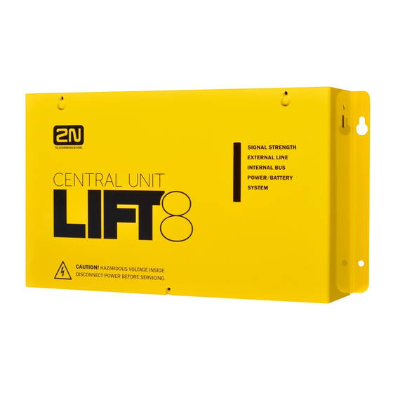
The audio units cannot be connected to a telephone line without the When shared by multiple shafts, the audio units cannot be connected without the and splitters. ® 918600 2N Lift8 Central Unit ® Figure: 2N Lift8 Central Unit For connection of up to 8 lifts to a GSM/UMTS/PSTN line. Including a power EURO cable and rechargeable battery. - Page 9 ® Figure: 2N Lift8 Splitter – lift audio unit interconnection ® 918610E 2N Lift8 audio unit – Cabin Universal (Normal version) ® Figure: 2N Lift8 audio unit – Cabin Universal Audio unit electronics for lift cabin buiiding in. Including speaker and microphone (HandsFree).
- Page 10 ® 918610EX 2N Lift8 audio unit – Cabin Universal – Cable Version (Contains LED, microphone and speaker connected to cables) ® Figure: 2N Lift8 audio unit – Cabin Universal – Cable Version ® 918611E 2N Lift8 audio unit – Machine Room/Control Centre ®...
- Page 11 ® 918612E 2N Lift8 audio unit – Shaft ® Figure: 2N Lift8 audio unit – Shaft Audio unit for cabin roof and shaft or cabin bottom. Robust yellow cover. HandsFree mode, Alarm button and Triphony, LED indicators. Not intended for use in the cabin.
- Page 12 ® 918650E 2N Lift8 GSM Module ® Figure: 2N Lift8 GSM Module For central unit connection via a mobile network. Optional data connection for remote system configuration. ® TELEKOMUNIKACE a.s., www.2n.cz...
- Page 13 ® 918651E 2N Lift8 UMTS Module ® Figure: 2N Lift8 UMTS Module For central unit connection via a mobile network. Optional data connection for remote system configuration. ® TELEKOMUNIKACE a.s., www.2n.cz...
- Page 14 ® 918652E 2N Lift8 PSTN Module ® Figure: 2N Lift8 PSTN Module For central unit connection via an analogue line. ® TELEKOMUNIKACE a.s., www.2n.cz...
- Page 15 ® 918653E 2N Lift8 VoIP Module ® Figure: 2N Lift8 VoIP Module For central unit connection via a VoIP line. ® TELEKOMUNIKACE a.s., www.2n.cz...
- Page 16 ® Cooperating 2N Applications ® 918700E 2N Lift8 Service Tool ® Figure: 2N Lift8 Service Tool ® Lift8 Service Tool application is intended for remote supervision and ® Lift8 configuration of the communicators. ® 918700E 2N Lift8 Control Panel ®...
- Page 17 ® 918700E 2N Lift8 Communicator ® Figure: 2N Lift8 Communicator ® Lift8 Communicator application is intended for receiving alarm calls by the dispatcher. ® 918700E 2N Lift8 Server ® Figure: 2N Lift8 Server ® Lift8 Server application processes check calls and mediates communication between the s and PC applications.
- Page 18 ® Associated 2N Products ® 918655E 2N Lift8 External Pictograms Driver ® Figure: 2N Lift8 External Pictograms Driver ® Transforms the Lift8 cabin LED outputs into universal pilot lamps. ® TELEKOMUNIKACE a.s., www.2n.cz...
-
Page 19: Upgrade
Description of changes version Firmware 1.0.0 1.0.0 Basic version Firmware 1.5.0 VoIP parameters added Internal splitter four-lift configuration option 1.5.0 (up to four cabin units can be connected to one internal splitter with lift 1–4 identification) Intercom function ® TELEKOMUNIKACE a.s., www.2n.cz... -
Page 20: Terms And Symbols Used
Useful information for quick and efficient functionality. Note Routines or advice for efficient use of the device. Future Functions, New Features The grey-marked text in this document designates the functions and features that are under preparation or development at present. ® TELEKOMUNIKACE a.s., www.2n.cz... -
Page 21: Description And Installation
2.3 Audio Unit – Cabin Universal 2.4 Audio Unit – Machine Room 2.5 Audio Unit – Shaft 2.6 PSTN Module 2.7 GSM/UMTS Module 2.8 VoIP Module Each subsection includes: Description of Components Before You Start Fitting Electrical Wiring ® TELEKOMUNIKACE a.s., www.2n.cz... -
Page 22: Pstn/Gsm/Umts/Voip Central Unit
2.1 PSTN/GSM/UMTS/VoIP Central Unit Description Figure: Central Unit ® TELEKOMUNIKACE a.s., www.2n.cz... - Page 23 Figure: Central Unit Indication Elements ® TELEKOMUNIKACE a.s., www.2n.cz...
- Page 24 (normally open) 4 … main bus audio - 5 … main bus data 6 … main bus data - There are a USB connector and reset button to the right of the (see the figure below): ® TELEKOMUNIKACE a.s., www.2n.cz...
- Page 25 Do not keep your PC connected for a long time unless necessary to reduce the computer damage due voltage surge from the telephone line during storms, for example. Warning Do not open the CU during the warranty period. Open the only to replace the rechargeable batteries after the warranty period. ® TELEKOMUNIKACE a.s., www.2n.cz...
- Page 26 On an easily accessible place there is a risk of telephone line misuse or SIM card misappropriation . is mounted on a wall with the included wall plugs and screws. ® TELEKOMUNIKACE a.s., www.2n.cz...
- Page 27 Do not disconnect the wire unless there is a reason to do so! Interconnect the rechargeable batteries and connect them with the motherboard using a FASTON cable (see the figure below). Mind the polarity. ® TELEKOMUNIKACE a.s., www.2n.cz...
- Page 28 1 h is guaranteed only if up to 20 audio units are connected in the system. The required 1h backup is not guaranteed if more than 20 audio units are installed. ® TELEKOMUNIKACE a.s., www.2n.cz...
- Page 29 Splitter – CU Bus Connection Interconnect the and splitter using a 6-wire main bus (power + - , audio + - , data + - ). Mind the polarity. ® TELEKOMUNIKACE a.s., www.2n.cz...
- Page 30 With a tow cable, consider the cable length too. With special cables (to the cabin), use the neighbouring wires and make sure that the nearest surrounding wires do not radiate interference (power wire, video signal etc.). ® TELEKOMUNIKACE a.s., www.2n.cz...
- Page 31 Notify the telephone network provider of your Lift8 installation and submit certification upon request. Your follow-up wiring must comply with the relevant safety regulations. You are recommended to secure your cabling against pirate connection (with a telephone lock, e.g.). ® TELEKOMUNIKACE a.s., www.2n.cz...
- Page 32 Other recommendations: ® Make an agreement with the PBX owner regarding operating costs (2N Lift8 outgoing calls are billed at the owner‘s expense with the exception of free calls via “green lines”).
- Page 33 PSTN line during the lift fitting time. In this case do not enable the lift blocking function until the telephone line is connected. VoIP VoIP is the cheapest solution where a reliable Internet connection is available. ® TELEKOMUNIKACE a.s., www.2n.cz...
-
Page 34: Splitter
The splitters are connected in series, i.e. one after another (never in parallel), to avoid system instability. A termination resistor (jumper) is mounted on the last splitter (furthest from the ® Figure: 2N Lift8 Splitter Caution Local power supply is not supported yet. ® TELEKOMUNIKACE a.s., www.2n.cz... - Page 35 Interconnect the splitter and Audio Units using a two-wire bus. Mind the polarity. Audio unit bus 1 … Bus for Audio Units + 2 … Bus for Audio Units - Address Configuration Configure the splitter address for the given lift using a 10-position switch 0–9 (see the figure). ® TELEKOMUNIKACE a.s., www.2n.cz...
- Page 36 There is one more pin between the main bus connector and lift number configuration, which helps you configure the termination resistance on the last splitter connected (the furthest from the The termination resistance jumper is disabled by default. ® TELEKOMUNIKACE a.s., www.2n.cz...
-
Page 37: Audio Unit - Cabin Universal
ALARM button; illuminated pictogram “Request received”; illuminated pictogram “Connection made”. The above mentioned elements have been located as required by the applicable regulations. There must be free space of at least 65×130×20 mm behind the panel. ® TELEKOMUNIKACE a.s., www.2n.cz... - Page 38 Electronics Mounting This Audio Unit is intended for mounting behind the lift control panel. Typically, the panel is ready for installation as shown in the drawing below: Figure: Mounting Hole Dimensions for Audio Unit – Cabin Universal ® TELEKOMUNIKACE a.s., www.2n.cz...
- Page 39 May I place the speaker on the cabin ceiling? This placement is not recommended. May I use a longer cable to the speaker? For the speaker yes, but we do not recommend it for the microphone. ® TELEKOMUNIKACE a.s., www.2n.cz...
- Page 40 Two LED signal lamps (other side) Audio Unit position 1. (yellow) Request received ALARM and CANCEL negation 2. (green) Connection confirmed Note If external LEDs are connected to connectors 7 and 8, LED indicators 1 and 2 will not be shining. ® TELEKOMUNIKACE a.s., www.2n.cz...
- Page 41 3 – under the cabin, 4 – shaft bottom). Configure the required changes as printed on the electronics cover. If you have removed the cover, put it back in the original position and tighten the screw. ® TELEKOMUNIKACE a.s., www.2n.cz...
- Page 42 The position-setting jumpers are employed exceptionally, e.g. where a certain audio unit type is used in a position other than normally intended. To recover the initial address setting, follow the drawing on the cover. Bus Connection Polarity must be maintained. ® TELEKOMUNIKACE a.s., www.2n.cz...
- Page 43 For activation by voltage connection, leave the jumper as it is (5th pin on jumper 12) – ALARM without jumper fitted (factory setting). For activation by voltage disconnection, fit the jumper (5th pin on jumper 12) – ALARM inverted – jumper fitted. ® TELEKOMUNIKACE a.s., www.2n.cz...
- Page 44 For activation by voltage disconnection, fit the jumper (6th pin on jumper 12) – CANCEL inverted – jumper fitted. Warning Ignoring the instructions above may lead to product damage. The CANCEL function only works when the cabin Audio Unit is set to the cabin position (default). ® TELEKOMUNIKACE a.s., www.2n.cz...
- Page 45 The induction loop has to be labelled with an appropriate symbol (ear) placed according to the applicable standards. ® TELEKOMUNIKACE a.s., www.2n.cz...
- Page 46 AC and DC power supplies can be used for powering the lamps. To protect the Car Unit and Pictogram Driver against damage caused by shorts, always use the included isolating tube when installing the device! ® TELEKOMUNIKACE a.s., www.2n.cz...
- Page 47 ® Lift8 External Pictogram Driver is in compliance with the essential requirements and other relevant provisions of the 1999/5/EC Directive. ® The Declaration of Conformity is attached to the basic module of 2N Lift8 and also available at www.2n.cz ®...
-
Page 48: Audio Unit - Machine Room
ALARM memory – set 2 (021–026). The ALARM button illumination (not required by default) helps you find and activate the Audio Unit easily in the dark. When you press the ALARM or TRIPHONY button, the function is called up ® TELEKOMUNIKACE a.s., www.2n.cz... - Page 49 7–8 jumpers for common machine room configuration Mounting The Audio Unit is typically mounted on a wall using the wall plugs and screws included in the delivery. Electrical Installation Description of Connectors There are 3 connectors to the right under the cover: ® TELEKOMUNIKACE a.s., www.2n.cz...
- Page 50 Audio Units with the lowest of the configured addresses. Caution Avoid the Audio Unit address duplicity Bus Connection Open the side door. Pull out the terminal from the connector, connect the wires and replace the terminal. Maintain the polarity. ® TELEKOMUNIKACE a.s., www.2n.cz...
- Page 51 Volume Configuration Open the protective door on the Audio Unit and adjust the volume using the trimmer Caution Use the trimmer to set the best acoustic properties eliminating feedback. Volume configuration only works in the HandsFree mode. ® TELEKOMUNIKACE a.s., www.2n.cz...
-
Page 52: Audio Unit - Shaft
Push the ALARM button, for example, when someone falls down the shaft. The Audio Unit calls the numbers configured in the ALARM memory – set 2 (021–026). The ALARM button illumination (not required by default) helps you find and activate the Audio Unit easily in the dark. ® TELEKOMUNIKACE a.s., www.2n.cz... - Page 53 The Audio Unit is not intended for outdoor installations. Electrical Installation Connectors The Audio Unit has one connector for bus connection. The second RJ–11 connector is used for handset connection. Both the connectors are under the side doors. ® TELEKOMUNIKACE a.s., www.2n.cz...
- Page 54 Audio Unit. Maintain polarity while connecting the Audio Unit to avoid Audio Unit error Caution The Audio Unit is powered via a 2-wire bus. Disconnection of these wires results in the Audio Unit switch-off. ® TELEKOMUNIKACE a.s., www.2n.cz...
- Page 55 Volume Configuration Open the protective door on the Audio Unit and adjust the volume using the trimmer. Caution Use the trimmer to set the best acoustic properties eliminating feedback. Volume configuration only works in the HandsFree mode. ® TELEKOMUNIKACE a.s., www.2n.cz...
-
Page 56: Pstn Module
6. Be careful while putting the module on the pins. Make sure that you have connected all the pins to the module connector. 7. Having fitted the pins into the connector correctly, you can fix the module using 2 bolts and 1 screw. ® TELEKOMUNIKACE a.s., www.2n.cz... - Page 57 8. Now connect the PSTN line. There are 2 options: using the RJ–11 connector; using a slide-on terminal board. Warning While fitting the module, make sure that all the pins are fitted correctly into the connector to avoid module damage. ® TELEKOMUNIKACE a.s., www.2n.cz...
-
Page 58: Gsm/Umts Module
6. Be careful while putting the module on the pins. Make sure that you have connected all the pins to the module connector. 7. While fitting the module mind the antenna connector. Make sure that it is pushed through the cover hole. ® TELEKOMUNIKACE a.s., www.2n.cz... - Page 59 Caution In places with a poor signal quality find an appropriate place or use a special (directional) antenna. Should you have DTMF transmission problems, set parameter 710 to 1 (for GSM modules only). ® TELEKOMUNIKACE a.s., www.2n.cz...
-
Page 60: Voip Module
6. Be careful while putting the module on the pins. Make sure that you have connected all the pins to the module connector. 7. Having fitted the pins into the connector correctly, you can fix the module using 2 bolts and 1 screw ® TELEKOMUNIKACE a.s., www.2n.cz... - Page 61 8. Now connect the VoIP line via the RJ–45 connector. Warning While fitting the module, make sure that all the pins are fitted correctly into the connector to avoid module damage.s ® TELEKOMUNIKACE a.s., www.2n.cz...
-
Page 62: System Configuration
3. System Configuration The system is supplied pre-configured. ® This section describes the Lift8 configuration. There are three ways how to progr ® am 2N Lift8 3.1 Programming 3.2 Table of Parameters (FW 1.5.2) ® TELEKOMUNIKACE a.s., www.2n.cz... - Page 63 ® TELEKOMUNIKACE a.s., www.2n.cz...
-
Page 64: Programming
Having entered the programming mode, you can change any programmable value(s) in any order. Proceed as follows: enter the function number and then the value. Use an asterisk as a separator or Enter. In general, the function has the following format: ® TELEKOMUNIKACE a.s., www.2n.cz... - Page 65 Today, voice transmission is prevailingly digital, using variable compression algorithms. Therefore, the DTMF signal to be transmitted is often distorted. Moreover, it may, in some cases, be transmitted through the so-called command channel, whose delay may differ from that of the speech channel. ® TELEKOMUNIKACE a.s., www.2n.cz...
- Page 66 In such cases, try some other equipment (a digital PBX, e.g.) or the machine room telephone set. If the machine room or PSTN programming attempts fail too, you have probably entered an invalid password. Programming via Service Tool ® Refer to the Service Tool section (Section 5) for details. ® TELEKOMUNIKACE a.s., www.2n.cz...
- Page 67 ® TELEKOMUNIKACE a.s., www.2n.cz...
-
Page 68: Table Of Parameters (Fw 1.5.2)
ALARM memory set Set 1 – count If 0 is configured, only the of automatic first number in the memory dialling 0–9 is called regardless of the cycles for count of saved numbers. ALARM ® TELEKOMUNIKACE a.s., www.2n.cz... - Page 69 Set 2 – up to 16 use the set 1 of ALARM ALARM mories. button digits: 0–9 memory 5 Set 2 – up to 16 ALARM button digits: 0–9 memory 6 Insert specific character in ALARM memory set ® TELEKOMUNIKACE a.s., www.2n.cz...
- Page 70 5 empty, use the set of digits: 0–9 ALARM memories. up to 16 Check call empty memory 6 digits: 0–9 Insert a character in check call memory Count of automatic dialling 0–9 cycles for checking call ® TELEKOMUNIKACE a.s., www.2n.cz...
- Page 71 PC (use the Service Tool). up to 16 Error call empty memory 5 digits: 0–9 up to 16 Error call empty memory 6 digits: 0–9 Insert specific character in fault reporting memory Count of automatic dialling 0–9 cycles for ERROR ® TELEKOMUNIKACE a.s., www.2n.cz...
- Page 72 Counted from the end of dialling. Used only with connected Delayed call 0–1000 s CANCEL input on the cabin Audio Unit. Max. Maximum TRIPHONY period TRIPHONY 10–9999 s 7200 s after which TRIPHONY is time terminated automatically. ® TELEKOMUNIKACE a.s., www.2n.cz...
- Page 73 (NOT after time the end of announcement). Min. cabin A low value is ALARM recommended for 10–9999 ms 100 ms button comfortable product pressing time testing. Machine room alerting 1–60 s time (siren) ® TELEKOMUNIKACE a.s., www.2n.cz...
- Page 74 10 message announcements in sequence by Cautions: sequence pressing 3 after call User messages confirmation recorded into the with up to 10 ® the aid of the 2N Service Call end Tool sequence announcements in sequence ® TELEKOMUNIKACE a.s., www.2n.cz...
- Page 75 (refer to Subs. 4.5 for details). 0 = disabled, 1 = enabled Enable (if the parameter is outgoing enabled, the machine room 0–1 machine Audio Unit can be used for room call outgoing public network calls). ® TELEKOMUNIKACE a.s., www.2n.cz...
- Page 76 Set the subnet bit mask. ** Set the IP address of the Default router/PC via which 1103 gateway communication outside the internal net is made. ** Set the DNS server IP 1104 DNS server address. ** ® TELEKOMUNIKACE a.s., www.2n.cz...
- Page 77 Service Tool version at www.2n.cz/Lift8 How to Record Announcement From PC ® ® Apply the Service Tool to record user announcements and numerals to ® Lift8. Refer to Subs. 5.3, Service Tool – Use for details. ® TELEKOMUNIKACE a.s., www.2n.cz...
-
Page 78: Function And Use
Here is what you can find in this section: 4.1 User Instructions 4.2 Control Centre Instructions 4.3 Function Description (for Advanced Users) 4.4 Call Confirmation Types 4.5 Lift Blocking Function 4.6 Four-Lift Version 4.7 Intercom Function ® TELEKOMUNIKACE a.s., www.2n.cz... -
Page 79: User Instructions
2 s) to display the machine room voicemenu . You can use the HandsFree mode or connect a handset to achieve better acoustic properties. Having entered the voice menu, you can select the following functions using the Audio Unit keypad. ® TELEKOMUNIKACE a.s., www.2n.cz... - Page 80 Press 2 to terminate the rescue process Press 3 to listen to your communicator info Press to return to the main menu Press # to end the call Note selection serves primarily for the configuration – refer to the Configuration section. ® TELEKOMUNIKACE a.s., www.2n.cz...
-
Page 81: Control Centre Instructions
Press 0 for connection with the last-calling Audio Unit, Enter the lift number X for connection with another Audio Unit, Press 9 for administration, information or rescue process, and Press # to end the call. ® TELEKOMUNIKACE a.s., www.2n.cz... - Page 82 This is due to the essential principle of the telephone line function where DTMF signalling is mixed with the call and thus may be masked by certain speech tones or noise. This, however, is not a defect of the product. ® TELEKOMUNIKACE a.s., www.2n.cz...
-
Page 83: Function Description (For Advanced Users)
Press the TRIPHONY button to enter the machine room voice menu get through to the other Audio Units of the same lift and set up triphony with the other shafts. ® TELEKOMUNIKACE a.s., www.2n.cz... - Page 84 A checking call can be sent to the control centre via PSTN, GSM, UMTS or VoIP. Set the values in parameters 071–076 and 981 (refer to Subs. 3.2, Table of Parameters). ® TELEKOMUNIKACE a.s., www.2n.cz...
- Page 85 Press 0 in the voice menu for connection with the last-calling Audio Unit. Incoming Call Voice Menu Welcome, this is a 2N Lift 8 communicator Press 0 to dial the last-calling Audio Unit Enter the lift number X to dial another Audio Unit...
- Page 86 = put in queue S = suspends ongoing activity Automatic Checking Call Answering ® A control centre with a PC workplace with the Lift8 server receives calls ® automatically as configured. Configure the server using the Lift8 Control Panel ® TELEKOMUNIKACE a.s., www.2n.cz...
- Page 87 The configured maximum call time has been exceeded (parameter 912). 10 seconds before the expiry, plays “Caution, the call is ending” for you to extend the call with symbol has been received. The time limit has expired during programming. A higher-priority call request has arrived. ® TELEKOMUNIKACE a.s., www.2n.cz...
-
Page 88: Call Confirmation Types
("Connection confirmed") and mutes the currently played announcement. The call goes on for the maximum DTMF char call time as configured. These digits are interpreted as control characters (refer to Subs. , Tone Dialling Control during Call). ® TELEKOMUNIKACE a.s., www.2n.cz... - Page 89 Used wherever the counterparty is equipped with the required SW. When the line is answered, a DTMF string is sent and the lift is identified. The call is either switched to voice communication (alarm call) or confirmed automatically and terminated (check call), as the case may be. ® TELEKOMUNIKACE a.s., www.2n.cz...
- Page 90 Having received a DTMF string, the lift recognises the protocol used and responds accordingly. Warning may have troubles detecting DTMF characters and recognising the protocol in places with a poor signal quality. If such troubles occur, we recommend you to change the CPC/P100 (3/4) settings. ® TELEKOMUNIKACE a.s., www.2n.cz...
-
Page 91: Lift Blocking Function
1 minute at least (PSTN, VoIP). a power supply is connected to recharge the battery. Caution This function may be mandatory if the applicable regulations valid for the country and time of installation require so. ® TELEKOMUNIKACE a.s., www.2n.cz... -
Page 92: Four-Lift Version
Normal 8-Lift Connection If you set parameter 994 to 0, you can connect up to 8 lift shafts and up to 5 Audio Units to each shaft (machine room, cabin roof, cabin, cabin bottom, shaft bottom). ® TELEKOMUNIKACE a.s., www.2n.cz... - Page 93 Figure: 8-Lift Configuration ® TELEKOMUNIKACE a.s., www.2n.cz...
-
Page 94: Intercom Function
For example, 011 – #8 means that a call to the machine room Audio Unit in the shaft of lift 8 is set in ALARM button memory 1. Setting options: Service Tool – enter # and the shaft number into parameters 011–016. ® TELEKOMUNIKACE a.s., www.2n.cz... - Page 95 Audio Unit with calling via the PSTN, GSM, UMTS and VoIP networks (depending on the module used). To set up a check call to a machine room Audio Unit, you can set the number as described in the Alarm – Intercom subsection above. ® TELEKOMUNIKACE a.s., www.2n.cz...
-
Page 96: Service Tool
5.1 Installation and Login 5.2 Introduction to Application 5.3 Use ® Refer to the Lift8 product pages at www.2n.cz , download section, fo r the latest FW version . You can use this link rom the online manual. ® TELEKOMUNIKACE a.s., www.2n.cz... -
Page 97: Installation And Login
Then you will also be asked whether the configuration files should be removed and the whole application with a new, empty database should be installed. ® Now the Lift8 Service Tool Setup Wizard has been launched. Follow the wizard ® instructions. Select the Lift8 Service Tool... - Page 98 ® Connect. The Lift8 Service Tool automatically finds the connected on the PC and starts downloading parameters and logs. Having completing the download, the 2N ® Lift8 Service Tool is ready for work. Warning ® Make sure that the USB port driver for the...
- Page 99 Caution Default values for connection: Username: Admin Password: 2n Port: 7007 Username: Admin Password: 2n ® TELEKOMUNIKACE a.s., www.2n.cz...
-
Page 100: Introduction To Application
® Figure: Lift8 Service Tool Window The Main menu contains three pop-up menus. The Device menu helps you connect to or disconnect from the . - Page 101 The section informs you of the line state and type, IP module parameters, IP address or address obtained from the DHC server, network mask, default gateway and DNS server. Finally, like with the GSM / UMTS ® TELEKOMUNIKACE a.s., www.2n.cz...
- Page 102 HW connected. The lower part of the application includes the Logout button (to the right) and other important controls, which may be different in different menus. The table below describes all the buttons available in the application. ® TELEKOMUNIKACE a.s., www.2n.cz...
- Page 103 Connect logs in the user to the configured Disconnect device logs out the currently logged-in user from the Find (CTRL+F) enables search in the log. Set the string (word) to be searched in the window. ® TELEKOMUNIKACE a.s., www.2n.cz...
- Page 104 ® Print HW setup – diagram helps you print out the current Lift8 HW settings as an image. ® Print HW setup – text helps you print out the current Lift8 HW settings as a text.
- Page 105 When all the parameters have been saved, the voice message will be deleted from the too. Open from file and save to device opens a file viewer for you to select the licence file for your This file will be downloaded to the upon confirmation. ® TELEKOMUNIKACE a.s., www.2n.cz...
-
Page 106: Use
Configuration Parameters Having logged in to the as described in the preceding subsection, you get into the main configuration menu. The Parameters – Basic menu includes the table of all the 2N ® Lift8 parameters including their codes. Refer to Subs. - Page 107 You can also click anywhere in the table with your right mouse button to display the context menu and delete the active filters. Figure: Filtration Setting Result Each table row is equipped with a hint including parameter description for convenience. ® TELEKOMUNIKACE a.s., www.2n.cz...
- Page 108 Advanced settings to enable/disable message types and assign colours for easier log displaying and other advanced options. See below for details. The logs should only be analysed by duly trained persons or your Technical Support department. ® TELEKOMUNIKACE a.s., www.2n.cz...
- Page 109 Refresh rate in seconds and select Auto scroll to view the last (most recent) log row all the time. Figure: Advanced Settings Menu The last two buttons help you load and save your configuration onto your PC disk for later use. ® TELEKOMUNIKACE a.s., www.2n.cz...
- Page 110 User Messages User Messages helps you replace the default system announcements with user ® messages. Load these messages from a file or, in the correct format, via the 2N Lift8 Service Tool. Use the microphone connected to your PC to record the messages.
- Page 111 Thus, optimise the message time to record all of your messages. Device ® The Device menu provides information on the Lift8 Central Unit connected: basic parameters and text/graphic diagram of available Audio Units and splitters. In addition, you can upgrade the here too. ® TELEKOMUNIKACE a.s., www.2n.cz...
- Page 112 Lift8 Service Tool configuration too for future connections. Connected Units The Connected units menu provides a graphic diagram of all the units connected to 2N ® Lift8. The following controls are available: Refresh to update the display, Press HW setting (diagram/text) to print out the diagram/text of all the Audio Units and splitters connected to the given CU.
- Page 113 . Enter a greater portion of the IMSI code to specify the SIM cards to be used in ® one network. You can add up to 10 IMSI codes to the licence. Contact your 2N Lift8 supplier or the manufacturer's Technical Support department ( sales@2n.cz...
- Page 114 If your does not include any licence file, its function is not limited and the inserted SIM card can log in to the provider's network, yet with some limitations (roaming, e.g.). ® TELEKOMUNIKACE a.s., www.2n.cz...
-
Page 115: Server
Here is what you can find in this section: 6.1 Installation and Licensing 6.2 Use ® Refer to the Lift8 product pages at www.2n.cz, download section, for the latest FW version. You can use this link from the online manual. ® TELEKOMUNIKACE a.s., www.2n.cz... -
Page 116: Installation And Licensing
Make sure that the port is accessible from the LAN (see the Note above) ® and correctly set in all the applications. Now the wizard is ready to install your 2N Lift8 Server . It displays an overview of the settings. Check them carefully as you will not be able to modify them after installation unless you re-install the application! If you detect an error, press Back to return to the error window. - Page 117 Licensing ® All the Lift8 Server functions are subject to licence. Upon your first PC installation of the application, you will get a trial licence for 800-hour operation and 50-user and 50-lift (CU) connection. Caution ® Every Lift8 Server restart increments the hour counter by 1.
- Page 118 If you install or start the VPN software, the primary network card will change and the server ID will change too. As a result, the existing licence will become invalid and you will not be able to log in to the server! ® TELEKOMUNIKACE a.s., www.2n.cz...
-
Page 119: Use
The database also includes a list of authorised users, which, depending on their user roles, can connect to the server, change configuration settings ® ® and/or process incoming alarm calls via the Lift8 Control Panel Lift8 Communicator ® Lift8 Server integrates a SIP station which can be assigned up to 8 independent accounts and process up to 32 parallel calls. - Page 120 Database import may only be executed when the server is stopped. If the server is running, the program identifies any importing attempt as an error. Enter the following command to stop the server: C:\Program Files\2N TELEKOMUNIKACE\ 2N Lift8\Server\l8_config.exe –cStopServer ® TELEKOMUNIKACE a.s., www.2n.cz...
- Page 121 If the database includes a high number of users and terminals, the table import will take a few minutes. Restart the server after every successful database import using the following command: C:\Program Files\2N TELEKOMUNIKACE\ 2N Lift8\Server\l8_config.exe –cStartServer Setting Options The l8_config program provides numerous server settings; see the long list below. parameters...
- Page 122 –sMaxLift sets the maximum count of lifts to be connected to the server at the same time. The maximum count is based on the licence. –sResetAdmin resets the Admin password to default '2n'. Server Commands –cStartServer starts the l8 server.
-
Page 123: Control Panel
Here is what you can find in this section: 7.1 Installation and Login 7.2 Introduction to Application 7.3 Use ® Refer to the Lift8 product pages at www.2n.cz, download section, for the latest FW version. You can use this link from the online manual. ® TELEKOMUNIKACE a.s., www.2n.cz... -
Page 124: Installation And Login
Then you will also be asked whether the configuration files should be removed or the whole application with a new, empty database should be installed. ® Now the Lift8 Control Panel Setup Wizard has been launched. Follow the ® wizard instructions. Select the Lift8 Control Panel... - Page 125 This connection cannot be removed. If you use one and the same PC for ® your Lift8 Control Panel and server, you can make use of these pre-settings ® and click the Connect icon. The Lift8 Control Panel will log in to the local server.
- Page 126 Caution Important! A default user with administrator login is created during the ® Lift8 Server installation to get connected to the server and configure the other users. The default user uses the following login data: Name: Admin Password: 2n...
-
Page 127: Introduction To Application
® Figure: Lift8 Control Panel Window The Main menu contains three pop-up menus. The Server menu helps you disconnect from the server or terminate the application. You will always be warned before logout or termination against data loss. - Page 128 Find the Logout button in the right-hand bottom corner and various important control buttons in the lower part of the application. The table below describes all the buttons available in the application. ® TELEKOMUNIKACE a.s., www.2n.cz...
- Page 129 (marked with a distinct red frame). Undo helps undo all changes made since the last saving. Create lift card helps you add a lift card to the database by adding a central unit. ® TELEKOMUNIKACE a.s., www.2n.cz...
- Page 130 Remove plan helps you remove the selected plan. Change plan updates the plan stored by storing a new map under the same name. Download plan helps you save the selected plan to a local disk. ® TELEKOMUNIKACE a.s., www.2n.cz...
- Page 131 Export helps you export the table in the currently displayed menu. ® TELEKOMUNIKACE a.s., www.2n.cz...
-
Page 132: Use
The function requires no confirmation and starts searching the database the moment you enter the first character. Add more characters to refine the filter until you find the required lift. Figure: Lifts Menu ® TELEKOMUNIKACE a.s., www.2n.cz... - Page 133 ® A functional lift: SingleTalk 2N LiftNet or Unknown, probably ® supplied by another manufacturer and able to communicate with the 2N Lift8 Server via CPC / P100. ® A functional Lift8 lift. The red chain below the icon indicates the state of ®...
- Page 134 Lifts Select a lift to open an extensive menu level with lift identification forms, check call evaluations, maps and local plans of the building where the lift is installed. Let us describe each of the forms. ® TELEKOMUNIKACE a.s., www.2n.cz...
- Page 135 Description item: location, purpose, specific settings and so on. Figure: Lifts – General Menu ® The Check call period specifies the check call timeout. The lift can call the 2N Lift8 Server any time within this timeout, but having exceeded this value, it will be marked as defective.
- Page 136 Lifts – Users Menu Checking Calls ® The Check(ing) calls menu includes a table of all the check calls received by the 2N Lift8 Server from lift addition until now. Click the filter button at each column to use filtration for call history search. Refer to the Calls subsection for details. The table...
- Page 137 If the address is incorrect, change it here. The change will appear in the General menu too. Click Check address to set a new address and press Save to add the address to the database. ® TELEKOMUNIKACE a.s., www.2n.cz...
- Page 138 A phone number is displayed for each lift too. Select an option in the Available plans to change the lift plan. Click Save to confirm the settings. ® TELEKOMUNIKACE a.s., www.2n.cz...
- Page 139 (green) and non-functional lifts due to a check call failure (red). Zoom the map in/out. See the figure below for a map view. Re-click the Global map button to quit the global map menu. ® TELEKOMUNIKACE a.s., www.2n.cz...
- Page 140 The same applies to the assigned lifts. Now choose a location on your disc and click Save to save the exported data. See the figure below for the exporting forms from the two menus. Figure: Lift and User Table Export ® TELEKOMUNIKACE a.s., www.2n.cz...
- Page 141 Contact number, Email, Company and Role. The following options are available: Administrator, Technician, Own role (see below for setting). New users are created as Dispatchers by default. Click Save to add the parameters to the database. ® TELEKOMUNIKACE a.s., www.2n.cz...
- Page 142 You can view the check call results and set some of the lift parameters depending on your role setting. Select a lift from the list and click Add lift to add a lift. Click Delete to remove a lift. Click Save to confirm the settings. ® TELEKOMUNIKACE a.s., www.2n.cz...
- Page 143 SIP Settings Every user (Technician/Dispatcher) must be assigned a SIP line, i.e. an account ® registered with a SIP provider or the PBX used for login via the 2N Lift8 Communicator . When you log in to the application, your line will be registered and ®...
- Page 144 See the table below for function details. Click Delete to remove a role. If a role disables a user to view or configure a menu, the menu will not be displayed to the user. ® TELEKOMUNIKACE a.s., www.2n.cz...
- Page 145 If you are editing (updating) rights for an existing role, the users concerned will be logged out when the new parameters have been saved. You will be informed of this by a dialogue window with confirmation. ® TELEKOMUNIKACE a.s., www.2n.cz...
- Page 146 The function requires no confirmation and starts searching the database the moment you enter the first character. Add more characters to refine the filter until you find the required group. Click on the group to open further settings; see the figure below. ® TELEKOMUNIKACE a.s., www.2n.cz...
- Page 147 Reject Accept and send 5 Confirm with 1 a 5 CPC Antenna, CPC KONE P100. Plan is the last parameter for you to choose a map of the building. Click Save to confirm the settings ® TELEKOMUNIKACE a.s., www.2n.cz...
- Page 148 Save to assign the role to all the users in the group. Now assign the lifts to be administered to this group of users in the Lifts menu. Figure: Groups – Users Menu ® TELEKOMUNIKACE a.s., www.2n.cz...
- Page 149 Proxy server of your own, contact your network administrator for correct settings. Caution ® Set the SIP lines in the Lift8 Server! Use the settings of the PC on which the server is installed instead of your PC settings. Your PC settings will be applied only if the server runs locally.
- Page 150 The Plans menu helps you manage plans of the buildings in which the lifts are installed. Assign the plans to the selected lift and mark the lift position in the Lifts menu. This ® information will then be displayed to the Lift8 Communicator operators. ® TELEKOMUNIKACE a.s., www.2n.cz...
- Page 151 Click Add plan to open a file browser and select the file to be added. Refer to the right part of the screen for the figure to be imported. Click Save to confirm the new plan. ® All the saved plans are stored in the Lift8 Server and accessible to all the logged-in users. Caution If, contrary to the figure, information is displayed instead of the plan list, check the plan storage on the server.
- Page 152 Click Show files to view the files and plans stored on the disc. Their names correspond with the server database key. You can also see the file size and delete any file in this window. ® TELEKOMUNIKACE a.s., www.2n.cz...
- Page 153 Figure: Filtration Setting Result The Calls menu is the only menu to include the Paste screen button. Push the button to ® TELEKOMUNIKACE a.s., www.2n.cz...
- Page 154 (Audio Unit) that initiated the alarm call. Such a call is then considered a correctly processed alarm call. The last icon signals that the confirmed alarm call has been transferred to another dispatcher or a technician. ® TELEKOMUNIKACE a.s., www.2n.cz...
- Page 155 See above for details. The table provides the following information: call date/time, phone number, serial number if CPC/P100 was successfully used, lift name and check call result. See the figure below. ® TELEKOMUNIKACE a.s., www.2n.cz...
- Page 156 Lift8 Server if made via the Lift8 Communicator . Click the filter button at each column to use filtration for call history search. See above for details. The table provides the following information: call date/time, called phone number, calling user (agent) name and note if added by the user during the call.
- Page 157 Figure: Calls – Outgoing Calls Menu ® TELEKOMUNIKACE a.s., www.2n.cz...
-
Page 158: Communicator
Here is what you can find in this section: 8.1 Installation and Login 8.2 Introduction to Application 8.3 Use ® Refer to the Lift8 product pages at www.2n.cz, download section, for the latest FW version. You can use this link from the online manual. ® TELEKOMUNIKACE a.s., www.2n.cz... -
Page 159: Installation And Login
If you are the first user of the ® application, enter your login data as communicated to you by your 2N Lift8 administrator. It is easy to set the connection: enter the server IP address if you establish connection to a LAN or public network server. - Page 160 Login Screen ® Now click Connect to selected server to log in to the Lift8 Server Server login may take some time if you have an extensive database as the application has to download all the current tables. Be patient please and wait for completion.
- Page 161 ® TELEKOMUNIKACE a.s., www.2n.cz...
-
Page 162: Introduction To Application
In this subsection, we will show you the application menu layout and basic controls. ® ® Unlike the Lift8 Service Tool Lift8 Control Panel , the application has just one menu level. The first screen upon start includes the Lifts menu, which provides an overview of all the lifts assigned to the logged-in user. - Page 163 Keypad is used for call control via DTMF. When pressed, each button sends the assigned DTMF character into the call. This function helps you confirm calls or program the CU. ® TELEKOMUNIKACE a.s., www.2n.cz...
- Page 164 ® TELEKOMUNIKACE a.s., www.2n.cz...
-
Page 165: Use
Telephoning is the main function of the application. If the user SIP line cannot be registered, the user will not be able to log in. In that case, ask ® your system administrator to check the SIP line settings in the 2N Lift8 Control Panel... - Page 166 (Timestamp), call-processing Agent and Note added during the alarm call. The Checking call table shows all check calls from the given lift since lift addition to the database. Each record includes its date/time and result. ® TELEKOMUNIKACE a.s., www.2n.cz...
- Page 167 Contacts ® The left section of the Contacts menu displays a list of all users configured in the 2N Lift8 system. Click a user to open its card. The following information is displayed in the middle of the window: Username, Firstname, Surname and Contact number. If the user is assigned a contact number, just click Call to set up a call to this user.
- Page 168 The last table column Note shows the note entered by the dispatcher during the call. Figure: Calls Menu Click the filter button at each column to use filtration for call search and combine the ® TELEKOMUNIKACE a.s., www.2n.cz...
- Page 169 Every incoming call to a dispatcher/technician number is signalled with an automatic switch to the Incoming calls window and pop-up of an Incoming call window in the ® left-hand bottom corner of the screen. This is useful when the 2N Lift8 Communicator display is hidden under another application as the Incoming call window is always on the top.
- Page 170 DTMF character into the call. If the lift address is completed, the lift location is displayed on the map below the keypad. Use the slider in the left-hand upper corner to zoom in/out. ® TELEKOMUNIKACE a.s., www.2n.cz...
- Page 171 The Outgoing call window provides identical formats and functions as the Incoming call window. Click Transfer to transfer an active call to one of the Available dispatchers/technicians, ® i.e. those who are online logged in to the Lift8 system; see the figure below. ® TELEKOMUNIKACE a.s., www.2n.cz...
- Page 172 This type of transfer is called call transfer with hang-up, i.e. your call is terminated, the caller gets the ringing tone again and this call will alert the dispatcher's line selected by you. ® TELEKOMUNIKACE a.s., www.2n.cz...
-
Page 173: Maintenance
9. Maintenance This section describes the product maintenance and FW upgrade. 9.1 Operation Interruption and Battery Replacement 9.2 Firmware Upgrade ® TELEKOMUNIKACE a.s., www.2n.cz... -
Page 174: Operation Interruption And Battery Replacement
The product can be stored for a maximum of 1 week without recharging and for 1 month after full charging Never leave the rechargeable batteries flat longer than needed. If the battery is completely flat, recharge it as soon as possible ® TELEKOMUNIKACE a.s., www.2n.cz... - Page 175 Always remember that the state of the batteries is essential for the system operation. ® TELEKOMUNIKACE a.s., www.2n.cz...
-
Page 176: Firmware Upgrade
Back up your configuration, execute upgrade and factory default reset and upload the configuration into the device (new ranges and default values will be used in the new FW version). Check the device time after upgrade. ® TELEKOMUNIKACE a.s., www.2n.cz... -
Page 177: Technical Parameters
All the product parameters comply with TBR-21 on condition that the product is to be operated as a single line terminal, i.e. no parallel connection with any other equipment is allowed. Line interference and noise picked up by the L8 microphone are relevant factors. ® TELEKOMUNIKACE a.s., www.2n.cz... - Page 178 The manufacturer reserves the right to modify the product in order to improve its qualities. The product contains no environmentally harmful components. When the product's service life is exhausted, dispose of it in accordance with the applicable legal regulations. ® TELEKOMUNIKACE a.s., www.2n.cz...
-
Page 179: Supplementary Information
11. Supplementary Information ® This section provides supplementary information on the Lift8 product. Here is what you can find in this section: 11.1 Troubleshooting 11.2 List of Abbreviations 11.3 Regulations 11.4 General Instructions and Cautions ® TELEKOMUNIKACE a.s., www.2n.cz... -
Page 180: Troubleshooting
11.1 Troubleshooting For the most frequently asked questions refer to faq.2n.cz ® TELEKOMUNIKACE a.s., www.2n.cz... -
Page 181: List Of Abbreviations
PC applications. This code monitors the values entered in the applications, and in the event Validator of an error such as excessive length, forbidden character, incorrect format etc., warns the user. ® TELEKOMUNIKACE a.s., www.2n.cz... -
Page 182: Regulations
Regulation (EC) No. 1488/94 as well as Council Directive 76/769/EEC and Commission Directives 91/155/EEC, 93/67/EEC, 93/105/EC and 2000/21/EC Directive 2002/96/EC of the European Parliament and of the Council of 27 January 2003 on waste electrical and electronic equipment. ® TELEKOMUNIKACE a.s., www.2n.cz... -
Page 183: General Instructions And Cautions
The manufacturer also assumes no responsibility for additional costs incurred by the consumer as a result of making calls using a line with an increased tariff. ® TELEKOMUNIKACE a.s., www.2n.cz... - Page 184 Make sure that the devices to be disposed of are complete. Do not throw battery packs into fire. Battery packs may not be taken into parts or short-circuited either. ® TELEKOMUNIKACE a.s., www.2n.cz...
- Page 185 2N TELEKOMUNIKACE a.s. Modřanská 621, 143 01 Prague 4, Czech Republic Phone: +420 261 301 500, Fax: +420 261 301 599 E-mail: sales@2n.cz Web: www.2n.cz LŠ2016v1.5.2 ® TELEKOMUNIKACE a.s., www.2n.cz...
Need help?
Do you have a question about the Lift8 and is the answer not in the manual?
Questions and answers