Advertisement
Quick Links
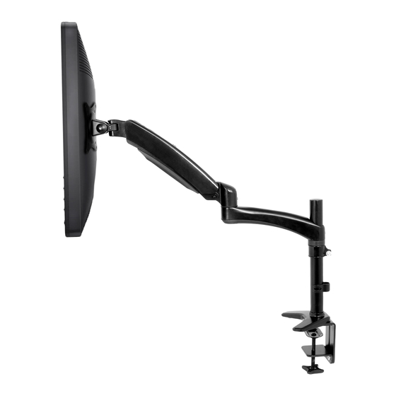
Pneumatic Arm Single Monitor Desk Mount
Instruction Manual
SKU: STAND-V001JB
Scan the QR code with your mobile device or follow the link
for helpful videos and specifications related to this product.
https://vivo-us.com/products/stand-v001jb
GET IN TOUCH | Monday-Friday from 7:00am-7:00pm CST
help@vivo-us.com
www.vivo-us.com
Chat live with an agent!
309-278-5303
Advertisement

Related Manuals for Vivo STAND-V001JB


Summary of Contents for Vivo STAND-V001JB
- Page 1 Pneumatic Arm Single Monitor Desk Mount Instruction Manual SKU: STAND-V001JB Scan the QR code with your mobile device or follow the link for helpful videos and specifications related to this product. https://vivo-us.com/products/stand-v001jb GET IN TOUCH | Monday-Friday from 7:00am-7:00pm CST help@vivo-us.com...
-
Page 2: Package Contents
WARNING! If you do not understand these directions, or if you have any doubts about the safety of the installation, please call a qualified technician. Check carefully to make sure there are no missing or defective parts. Improper installation may cause damage or serious injury. Do not use this product for any purpose that is not explicitly specified in this manual. -
Page 3: Tools Needed
TOOLS NEEDED DO NOT EXCEED WEIGHT CAPACITY. 13.2lbs Failure to do so may result in serious injury. (5.99kg) Phillips Screwdriver ASSEMBLY STEPS STEP 1 Loosen the clamp screw on Clamp and Pole (A) until opening is large enough to fit the edge of the desk. - Page 4 STEP 3 Adjust the locating ring to required height and tighten to support the arm. STEP 4 Slide the extension arm (C) onto the steel pole (A) until the arm (C) rests on top of the locating ring.
- Page 5 STEP 5 OPTION A: Flat Back Monitor Use four M4x8 screws (I) or M4x12 screws (J) to secure the Spring Arm (B) to the monitor via mounting holes. OPTION B: Curved Back Monitor Place four plastic spacers (L) between the Spring Arm (B) and the monitor, then use four M4x30 screws (K) to secure the Spring Arm (B) to the monitor via mounting holes.
- Page 6 STEP 6 Carefully place the spring arm (B) with the monitor onto the extension arm (C), and secure using the M6x25 spring bolt (F) and Plastic Cap (D). STEP 7 Use the 5mm Allen Key (H) to adjust the spring tension inside the arm (B) depending on the weight of your monitor.
- Page 7 STEP 8 Use the 3mm Allen Key (G) to adjust the arm swivel joints, and the 5mm Allen Key (H) to adjust the monitor swivel joint. Turn counter-clockwise to loosen and clockwise to tighten. S=3mm S=3mm S=5mm STEP 9 Insert the monitor cables into the cable covers on the underside of the arm (B). Leave enough slack to allow full adjustment and motion of the arm.
- Page 8 - 92% within < 3hr www.vivo-us.com : < 15 M AVG. RESOLUTION TIME (within office hrs) Chat live with an agent! : 5M 4S 309-278-5303 AVG. RESOLUTION TIME (within office hrs) FOR MORE VIVO PRODUCTS, CHECK OUT OUR WEBSITE AT: www.vivo-us.com...
Need help?
Do you have a question about the STAND-V001JB and is the answer not in the manual?
Questions and answers