
Related Manuals for Epson S5U13781R01C100


Summary of Contents for Epson S5U13781R01C100
- Page 1 S5U13781R01C100 Shield TFT Board Users Manual Document Number: X94A-G-010-01.02 Rev. 1.02...
- Page 2 Seiko Epson. Seiko Epson reserves the right to make changes to this material without notice. Seiko Epson does not assume any liability of any kind arising out of any inaccuracies contained in this material or due to its application or use in any product or circuit and, further, there is no representation that this material is applicable to products requiring high level reliability, such as, medical products.
-
Page 3: Table Of Contents
WQVGA Displays .......................... 9 QVGA Displays ........................... 11 Power, Clock and Reset .....................13 Power ............................13 Clock and Reset .......................... 14 Parts List ..........................15 Schematic Diagram ......................16 Change Record ........................17 Sales and Technical Support .....................18 Seiko Epson Corporation S5U13781R01C100 Shield Board (Rev.1.02) - Page 4 Seiko Epson Corporation S5U13781R01C100 Shield Board (Rev. 1.02)
-
Page 5: Introduction
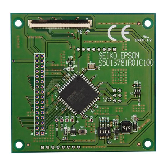
This manual describes the setup and configuration of the S1D13781 Shield TFT board, part number S5U13781R01C100, which includes an Epson S1D13781 Simple LCD Controller. The S1D13781 Shield TFT board is used to add a WQVGA (480x272) or QVGA (320x240) LCD display (not included on the board) to a microcontroller board such as: •... -
Page 6: Platform Support
The S1D13781 is configured to use the SPI host interface. The board will connect on the SPI bus to the Atmel MCU on the Arduino Due. S1D13781 Shield to Arduino Due Connections Seiko Epson Corporation S5U13781R01C100 Shield Board (Rev. 1.02) -
Page 7: Mbed Compatible Board Support
S1D13781 Shield Graphics Library is available for the mbed online compiler and is designed for use with compatible platforms (see https://developer.mbed.org/). More information on the following subjects can be found in the document “Using the S5U13781R01C100 Shield TFT Board with mbed Compatible Platforms”, document number X94A-G-011-xx, available at vdc.epson.com:... -
Page 8: Infineon Board Support
2.3.1 Connection to Infineon XMC4700 The S1D13781 Shield TFT board plugs into the Infineon XMC4700 board using the Arduino compatible headers shown in the following image. S1D13781 Shield to Infineon XMC4700 Connections Seiko Epson Corporation S5U13781R01C100 Shield Board (Rev. 1.02) -
Page 9: Lcd Displays Supported
To connect WQVGA displays, use connector CN1 which is located on the bottom of the board. The panel flex cable must have the contact pads facing toward the PCB. Typical WQVGA Panel Connection Seiko Epson Corporation S5U13781R01C100 Shield Board (Rev.1.02) - Page 10 S1D13781 Shield TFT board are required. The resistors are located on the bottom of the board. • Remove 0 ohm resistors R17, R19 and R21 • Solder 0 ohm resistors R18, R20, R22, R23 and R24 S1D13781 Shield TFT Board Modifications for Hantronix HDA430-3GH-1 WQVGA Seiko Epson Corporation S5U13781R01C100 Shield Board (Rev. 1.02)
-
Page 11: Qvga Displays
Microtips MTF-TQ35SP741-AV To connect QVGA displays, use connector CN2 which is located on top of the board. The panel flex cable must have the contact pads toward the PCB. Typical QVGA Panel Connection Seiko Epson Corporation S5U13781R01C100 Shield Board (Rev.1.02) - Page 12 LCD signals, but is unpopulated on the board. If the connector is added it allows the user to design and build adapter board to support a wide range of LCD display that are not directly supported. Generic LCD Connector, J4 (Unpopulated) Seiko Epson Corporation S5U13781R01C100 Shield Board (Rev. 1.02)
-
Page 13: Power, Clock And Reset
Shield TFT board. These resistors are located on the top of the board. • Remove 0 ohm resistor R15 and R13 • Solder 0 ohm resistors R16 and R14 Required Modifications for +5V Power for Backlight Seiko Epson Corporation S5U13781R01C100 Shield Board (Rev.1.02) -
Page 14: Clock And Reset
Power, Clock and Reset Clock and Reset The LCD controller has the clock provided by an Epson 1MHz oscillator, Y1. The LCD controller can be reset by a reset button, SW1, on the S1D13781 Shield TFT board. The following picture shows the position of each component. -
Page 15: Parts List
RES 680 OHM 1/16W 1% 0402 SMD R1,R10,R25 RES 10.0K OHM 1/16W 1% 0402 SMD 100k RES 100K OHM 1/16W 1% 0402 SMD 100k_NP RES 100K OHM 1/16W 1% 0402 SMD / Do not buy, do not populate Seiko Epson Corporation S5U13781R01C100 Shield Board (Rev.1.02) -
Page 16: Schematic Diagram
Schematic Diagram Schematic Diagram Seiko Epson Corporation S5U13781R01C100 Shield Board (Rev. 1.02) -
Page 17: Change Record
Change Record X94A-G-010-01 Revision 1.02 - Issued: March 30, 2018 • Updated address/contact page • Updated Epson web page • Minor formatting changes X94A-G-010-01 Revision 1.01 - Issued: February 26, 2016 • Section 1, added references to mbed compatible and Infineon options •... -
Page 18: Sales And Technical Support
Sales and Technical Support Sales and Technical Support For more information on Epson Display Controllers, visit the Epson Global website. https://global.epson.com/products_and_drivers/semicon/products/display_controllers/ For Sales and Technical Support, contact the Epson representative for your region. https://global.epson.com/products_and_drivers/semicon/information/support.html Seiko Epson Corporation S5U13781R01C100 Shield Board...
Need help?
Do you have a question about the S5U13781R01C100 and is the answer not in the manual?
Questions and answers