
Subscribe to Our Youtube Channel
Related Manuals for Beckhoff KL1 Series


Summary of Contents for Beckhoff KL1 Series
- Page 1 Documentation KL1xxx Digital input terminals, 24 V DC Version: 1.0.0 Date: 2020-05-08...
-
Page 3: Table Of Contents
Table of contents Table of contents 1 Foreword .............................. 5 Notes on the documentation...................... 5 Safety instructions .......................... 6 Documentation issue status ...................... 7 2 Product overview............................ 8 KL1xxx terminal overview ........................ 8 KL1002, KL1012 - Introduction ...................... 9 2.2.1 KL1002, KL1012 – Technical data................... 10 2.2.2 KL1002 - LEDs and connection .................. - Page 4 Table of contents 6 TwinCAT .............................. 49 Programming ........................... 50 7 Appendix .............................. 51 Support and Service ........................ 51 Version: 1.0.0 KL1xxx...
-
Page 5: Foreword
EP1590927, EP1789857, EP1456722, EP2137893, DE102015105702 with corresponding applications or registrations in various other countries. ® EtherCAT is registered trademark and patented technology, licensed by Beckhoff Automation GmbH, Germany. Copyright © Beckhoff Automation GmbH & Co. KG, Germany. The reproduction, distribution and utilization of this document as well as the communication of its contents to others without express authorization are prohibited. -
Page 6: Safety Instructions
All the components are supplied in particular hardware and software configurations appropriate for the application. Modifications to hardware or software configurations other than those described in the documentation are not permitted, and nullify the liability of Beckhoff Automation GmbH & Co. KG. Personnel qualification This description is only intended for trained specialists in control, automation and drive engineering who are familiar with the applicable national standards. -
Page 7: Documentation Issue Status
Foreword Documentation issue status Version Comment 1.0.0 • Migration • Structure update • Technical data updated • Installation instructions for enhanced mechanical load capacity added • Revision status updated Firmware and hardware versions Documentation KL1002 KL1012 KL1104 KL1114 Version Firmware Hardware Firmware Hardware... -
Page 8: Product Overview
Product overview Product overview KL1xxx terminal overview Digital input terminals Terminal Number of inputs Nominal voltage Filter Comment 24 V 3 ms KL1002 [} 9] 24 V 0.2 ms KL1012 [} 9] 24 V 3 ms KL1104 [} 13] 24 V 0.2 ms KL1114 [} 13] 24 V 3 ms KL1402 [} 16] 24 V 0.2 ms KL1412 [} 16] 24 V 3 ms... -
Page 9: Kl1002, Kl1012 - Introduction
Product overview KL1002, KL1012 - Introduction Fig. 1: KL1002 Fig. 2: KL1012 KL1xxx Version: 1.0.0... -
Page 10: Kl1002, Kl1012 - Technical Data
Product overview Two-channel, digital input terminals, 24 V The KL1002 and KL1012 digital input terminals acquire the binary control signals from the process level and transmit them, in an electrically isolated form, to the higher-level automation unit. The KL1002 and KL1012 versions have input filters of different speeds. -
Page 11: Kl1002 - Leds And Connection
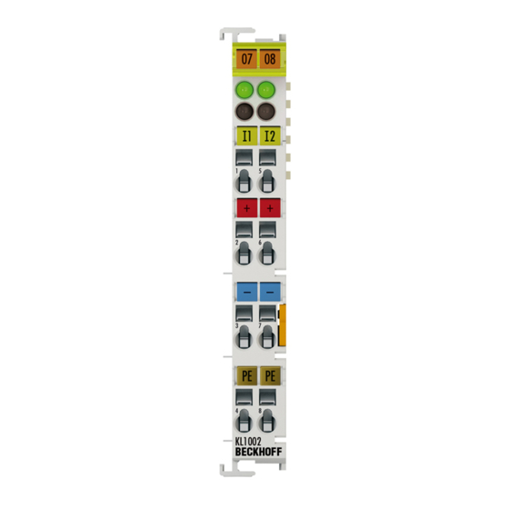
Product overview 2.2.2 KL1002 - LEDs and connection Fig. 3: KL1002 KL1002 - LEDs Color Meaning Signal LEDs 1 - 2 green Signal voltage "0" (-3 V ... 5 V) Signal voltage "1" (15 V ... 30 V) KL1002 - Connection Terminal point Description Name Input 1 Input 1... -
Page 12: Kl1012 - Leds And Connection
Product overview 2.2.3 KL1012 - LEDs and connection Fig. 4: KL1012 KL1012 - LEDs Color Meaning Signal LEDs 1 - 2 green Signal voltage "0" (-3 V ... 5 V) Signal voltage "1" (15 V ... 30 V) KL1012 - Connection Terminal point Description Name Input 1 Input 1 +24 V... -
Page 13: Kl1104, Kl1114 - Introduction
Product overview KL1104, KL1114 - Introduction Fig. 5: KL1104 Fig. 6: KL1114 KL1xxx Version: 1.0.0... -
Page 14: Kl1104, Kl1114 - Technical Data
Product overview Four-channel, digital input terminals, 24 V The KL1104 and KL1114 digital input terminals acquire the binary control signals from the process level and transmit them, in an electrically isolated form, to the higher-level automation unit. The KL1104 and KL1114 versions have input filters of different speeds. -
Page 15: Kl1104, Kl1114 - Leds And Connection
Product overview 2.3.2 KL1104, KL1114 - LEDs and connection Fig. 7: KL1104 KL1104, KL1114 - LEDs Color Meaning Signal LEDs 1 - green Signal voltage "0" (-3 V ... 5 V) Signal voltage "1" (15 V ... 30 V) KL1104, KL1114 - Connection Terminal point Description Name Input 1... -
Page 16: Kl1402, Kl1412 - Introduction
Product overview KL1402, KL1412 - Introduction Fig. 8: KL1402 Fig. 9: KL1412 Version: 1.0.0 KL1xxx... -
Page 17: Kl1402, Kl1412 - Technical Data
Product overview 2-channel digital input terminal 24 V , type 3 The KL1402 and KL1412 supplement the proven KL1404, KL1414, KL1408 und KL1418 digital input terminals with their type-3 specification. The current/voltage characteristics have been optimized for 2-wire sensors. The input current in low state is increased to a minimum value of 1.5 mA and therefore supports the majority of commercially available 2-wire sensors. -
Page 18: Kl1402, Kl1412 - Leds And Connection
Product overview 2.4.2 KL1402, KL1412 - LEDs and connection Fig. 10: KL1402 KL1402, KL1412 - LEDs Color Meaning Signal LED 1 - 2 green Signal voltage "0" (-3 V ... 5 V) Signal voltage "1" (15 V ... 30 V) KL1402, KL1412 - Connection Terminal point Description Name Input 1... -
Page 19: Kl1404, Kl1414, Kl1434 - Introduction
Product overview KL1404, KL1414, KL1434 - Introduction Fig. 11: KL1404 Fig. 12: KL1414 KL1xxx Version: 1.0.0... - Page 20 Product overview Fig. 13: KL1434 Four-channel, digital input terminals, 24 V The KL1404, KL1414 and KL1434 digital input terminals acquire the binary control signals (24 V) and transmit them, in an electrically isolated form, to the higher-level automation system. The Bus Terminals contain four channels that indicate their signal state by means of light emitting diodes. The KL1404, KL1414 and KL1434 versions have different input filters.
-
Page 21: Kl1404, Kl1414, Kl1434 - Technical Data
Product overview 2.5.1 KL1404, KL1414, KL1434 - Technical data Technical data KL1404, KS1404 KL1414, KS1414 KL1434, KS1434 Connection technology 2-wire Number of inputs Nominal voltage 24 V (-15 %/+20 %) Signal voltage ‘0’ -3 V to 5 V (EN 61131-2, type 1) -3 V to 5 V (EN 61131-2, type 2) Signal voltage ‘1’... -
Page 22: Kl1404, Kl1414 - Leds And Connection
Product overview 2.5.2 KL1404, KL1414 - LEDs and connection Fig. 14: KL1414 KL1404, KL1414 - LEDs Color Meaning Signal LED 1 - 4 green Signal voltage "0" (-3 V ... 5 V) Signal voltage "1" (15 V ... 30 V) KL1404, KL1414 - Connection Terminal point Description Name Input 1... -
Page 23: Kl1434 - Leds And Connection
Product overview 2.5.3 KL1434 - LEDs and connection Fig. 15: KL1434 KL1434 - LEDs Color Meaning Signal LED 1 - 4 green Signal voltage "0" (-3 V ... 5 V) Signal voltage "1" (11 V ... 30 V) KL1434 - Connection Terminal point Description Name Input 1 Input 1 +24 V... -
Page 24: Kl1408, Kl1418, Kl1488, Kl1498 - Introduction
Product overview KL1408, KL1418, KL1488, KL1498 - Introduction Fig. 16: KL1408 Fig. 17: KL1418 Version: 1.0.0 KL1xxx... - Page 25 Product overview Fig. 18: KL1488 Fig. 19: KL1498 KL1xxx Version: 1.0.0...
-
Page 26: Kl1408, Kl1418, Kl1488, Kl1498 - Technical Data
Product overview Eight-channel, digital input terminals, 24 V The digital input terminals KL1408 and KL1418 (positive switching) and KL1488 and KL1498 (negative switching) acquire the binary control signals from the process level and transmit them, in an electrically isolated form, to the higher-level automation unit. The Bus Terminals each contain eight channels, whose signal states are displayed by LEDs. -
Page 27: Kl1408, Kl1418 - Leds And Connection
Product overview 2.6.2 KL1408, KL1418 - LEDs and connection Fig. 20: KL1408 KL1408, KL1418 - LEDs Color Meaning Signal LED 1 - 8 green Signal voltage "0" (-3 V ... 5 V) Signal voltage "1" (15 V ... 30 V) KL1408, KL1418 - Connection Terminal point Description Name Input 1... -
Page 28: Kl1488, Kl1498 - Leds And Connection
Product overview 2.6.3 KL1488, KL1498 - LEDs and connection Fig. 21: KL1488 KL1488, KL1498 - LEDs Color Meaning Signal LED 1 - 8 green Signal voltage "0" (18 V ... 30 V) Signal voltage "1" (0 V ... 7 V) KL1488, KL1498 - Connection Terminal point Description Name Input 1... -
Page 29: Kl1862, Kl1862-0010, Kl1872 - Introduction
Product overview KL1862, KL1862-0010, KL1872 - Introduction Fig. 22: KL1862 Fig. 23: KL1872 KL1xxx Version: 1.0.0... -
Page 30: Kl1862, Kl1862-0010, Kl1872 - Technical Data
Product overview 16-channel digital input terminal with ribbon cable connection, 24 V The KL1862 and KL1872 digital input terminals offer a very compact design with their 16 channels. A 20-pin connector enables the secure connection of plug connectors using insulation displacement contact, as is usual for ribbon cables and special round cables. -
Page 31: Kl1862, Kl1872 - Leds And Connection
Product overview 2.7.2 KL1862, KL1872 - LEDs and connection Fig. 24: KL1862 KL1862, KL1872 - LEDs Color Meaning Signal LED 1 - 16 green Signal voltage "0" (-3 V ... 5 V) Signal voltage "1" (11 V ... 30 V) KL1862, KL1872 – Connection 2 x 10 pin connector RM 2.54 mm with locking mechanism for connecting a 2 x 10 pin plug connector (post socket with insulation displacement contact for ribbon cable);... -
Page 32: Mounting And Wiring
Mounting and wiring Mounting and wiring Installation on mounting rails WARNING Risk of electric shock and damage of device! Bring the bus terminal system into a safe, powered down state before starting installation, disassembly or wiring of the bus terminals! Assembly Fig. 25: Attaching on mounting rail The bus coupler and bus terminals are attached to commercially available 35 mm mounting rails (DIN rails... - Page 33 Mounting and wiring Disassembly Fig. 26: Disassembling of terminal Each terminal is secured by a lock on the mounting rail, which must be released for disassembly: 1. Pull the terminal by its orange-colored lugs approximately 1 cm away from the mounting rail. In doing so for this terminal the mounting rail lock is released automatically and you can pull the terminal out of the bus terminal block easily without excessive force.
- Page 34 Mounting and wiring Fig. 27: Power contact on left side NOTE Possible damage of the device Note that, for reasons of electromagnetic compatibility, the PE contacts are capacitatively coupled to the mounting rail. This may lead to incorrect results during insulation testing or to damage on the terminal (e.g. disruptive discharge to the PE line during insulation testing of a consumer with a nominal voltage of 230 V).
-
Page 35: Installation Instructions For Enhanced Mechanical Load Capacity
Mounting and wiring Installation instructions for enhanced mechanical load capacity WARNING Risk of injury through electric shock and damage to the device! Bring the Bus Terminal system into a safe, de-energized state before starting mounting, disassembly or wiring of the Bus Terminals! Additional checks The terminals have undergone the following additional tests: Verification Explanation... - Page 36 Mounting and wiring • The terminals of ESxxxx and KSxxxx series feature a pluggable connection level and enable steady wiring while replacing. • The High Density Terminals (HD Terminals) include electronics and connection level in a single enclosure and have advanced packaging density. Standard wiring (ELxxxx / KLxxxx) Fig. 28: Standard wiring The terminals of ELxxxx and KLxxxx series have been tried and tested for years.
- Page 37 Mounting and wiring High Density Terminals (HD Terminals) Fig. 30: High Density Terminals The Bus Terminals from these series with 16 terminal points are distinguished by a particularly compact design, as the packaging density is twice as large as that of the standard 12 mm Bus Terminals. Massive conductors and conductors with a wire end sleeve can be inserted directly into the spring loaded terminal point without tools.
-
Page 38: Wiring
Mounting and wiring 3.3.2 Wiring WARNING Risk of electric shock and damage of device! Bring the bus terminal system into a safe, powered down state before starting installation, disassembly or wiring of the Bus Terminals! Terminals for standard wiring ELxxxx/KLxxxx and for pluggable wiring ESxxxx/KSxxxx Fig. 31: Connecting a cable on a terminal point Up to eight terminal points enable the connection of solid or finely stranded cables to the Bus Terminal. -
Page 39: Shielding
Mounting and wiring Terminal housing High Density Housing Wire size width (single core wires) 0.08 ... 1.5 mm Wire size width (fine-wire conductors) 0.25 ... 1.5 mm Wire size width (conductors with a wire end sleeve) 0.14 ... 0.75 mm Wire size width (ultrasonically “bonded" conductors) only 1.5 mm Wire stripping length 8 ... -
Page 40: Atex - Special Conditions (Standard Temperature Range)
80°C at the wire branching points, then cables must be selected whose tempera- ture data correspond to the actual measured temperature values! • Observe the permissible ambient temperature range of 0 to 55°C for the use of Beckhoff fieldbus compo- nents standard temperature range in potentially explosive areas! •... -
Page 41: Atex - Special Conditions (Extended Temperature Range)
80°C at the wire branching points, then cables must be selected whose tempera- ture data correspond to the actual measured temperature values! • Observe the permissible ambient temperature range of -25 to 60°C for the use of Beckhoff fieldbus com- ponents with extended temperature range (ET) in potentially explosive areas! •... -
Page 42: Continuative Documentation About Explosion Protection
Explosion protection for terminal systems Pay also attention to the continuative documentation Notes on the use of the Beckhoff terminal systems in hazardous areas according to ATEX and IECEx that is available for download on the Beckhoff homepage https:\\www.beckhoff.com! Version: 1.0.0... -
Page 43: Ks2000 Configuration Software
KS2000 Configuration software KS2000 Configuration software KS2000 - Introduction The KS2000 configuration software permits configuration, commissioning and parameterization of bus couplers, of the affiliated bus terminals and of Fieldbus Box Modules. The connection between bus coupler / Fieldbus Box Module and the PC is established by means of the serial configuration cable or the fieldbus. Fig. 32: KS2000 configuration software Configuration You can configure the Fieldbus stations with the Configuration Software KS2000 offline. - Page 44 KS2000 Configuration software Commissioning The KS2000 software facilitates commissioning of machine components or their fieldbus stations: Configured settings can be transferred to the fieldbus modules by means of a download. After a login to the terminal station, it is possible to define settings in couplers, terminals and Fieldbus Box modules directly online. The same high-level dialogs and register access are available for this purpose as in the configuration phase.
-
Page 45: Access From The User Program
Access from the user program Access from the user program Examples of Register Communication The numbering of the bytes in the examples corresponds to the display without word alignment. 5.1.1 Example 1: reading the firmware version from Register 9 Output Data Byte 0: Control byte Byte 1: DataOUT1, high byte Byte 2: DataOUT1, low byte... - Page 46 Access from the user program • Bits 0.5 to 0.0 specify the register number 31 with 01 1111 • The output data word (byte 1 and byte 2) contains the code word (0x1235) for deactivating write protection. Input Data (answer of the bus terminal) Byte 0: Status byte Byte 1: DataIN1, high byte Byte 2: DataIN1, low byte...
- Page 47 Access from the user program CAUTION Observe the register description! The value of 0x0002 given here is just an example! The bits of the feature register change the properties of the terminal and have a different meaning, depend- ing on the type of terminal. Refer to the description of the feature register of your terminal (chapter Register description) regarding the meaning of the individual bits before changing the values.
- Page 48 Access from the user program Input Data (answer of the bus terminal) Byte 0: Status byte Byte 1: DataIN1, high byte Byte 2: DataIN1, low byte 0x9F (1001 1111 0xXX 0xXX Explanation: • The terminal returns a value as a receipt in the status byte that differs only in bit 0.6 from the value of the control byte.
-
Page 49: Twincat
The general use of hardware and software from the open PC world requires some checking: Unsuitable components can upset the PC system. Beckhoff integrates a handy display of the real-time jitter in order to provide administrators with a simple means of evaluating hardware and software. A system message during operation can draw attention to error states. -
Page 50: Programming
According to the requirement for operating resources, the TwinCAT software devices can be distributed: TwinCAT PLC programs can be executed on PCs and on Beckhoff Bus Terminal controllers. A "message router" manages and distributes all the messages, both in the system and via TCP/IP connections. PC systems can be connected to one another by TCP/IP;... -
Page 51: Appendix
Beckhoff's branch offices and representatives Please contact your Beckhoff branch office or representative for local support and service on Beckhoff products! The addresses of Beckhoff's branch offices and representatives round the world can be found on her internet pages: http://www.beckhoff.com You will also find further documentation for Beckhoff components there. - Page 52 List of illustrations List of illustrations Fig. 1 KL1002 ............................Fig. 2 KL1012 ............................Fig. 3 KL1002 ............................Fig. 4 KL1012 ............................Fig. 5 KL1104 ............................Fig. 6 KL1114 ............................Fig. 7 KL1104 ............................Fig. 8 KL1402 ............................Fig. 9 KL1412 ............................
Need help?
Do you have a question about the KL1 Series and is the answer not in the manual?
Questions and answers