
Subscribe to Our Youtube Channel
Related Manuals for Beckhoff KL3102


Summary of Contents for Beckhoff KL3102
- Page 1 Documentation KL3102, KL3112, KL3122 Dual-Channel Analog Input Terminals,-10 V to +10 V, 0/4 mA to 20 mA Version: Date: 2019-10-15...
-
Page 3: Table Of Contents
Connection system ...................... 20 3.4.2 Wiring.......................... 23 3.4.3 Shielding .......................... 24 KL3102 - Connection and LED description .................. 25 KL3112, KL3122 - Connection and LED description ............... 26 ATEX - Special conditions (standard temperature range) ............... 27 ATEX Documentation ........................ 28 4 Configuration Software KS2000 ...................... 29 KS2000 - Introduction ........................ 29... - Page 4 Table of contents Version: 3.2 KL3102, KL3112, KL3122...
-
Page 5: Foreword
EP1590927, EP1789857, EP1456722, EP2137893, DE102015105702 with corresponding applications or registrations in various other countries. ® EtherCAT is registered trademark and patented technology, licensed by Beckhoff Automation GmbH, Germany. Copyright © Beckhoff Automation GmbH & Co. KG, Germany. The reproduction, distribution and utilization of this document as well as the communication of its contents to others without express authorization are prohibited. -
Page 6: Safety Instructions
All the components are supplied in particular hardware and software configurations appropriate for the application. Modifications to hardware or software configurations other than those described in the documentation are not permitted, and nullify the liability of Beckhoff Automation GmbH & Co. KG. Personnel qualification This description is only intended for trained specialists in control, automation and drive engineering who are familiar with the applicable national standards. -
Page 7: Documentation Issue Status
1 - hardware version 1 Beckhoff Identification Code (BIC) The Beckhoff Identification Code (BIC) is increasingly being applied to Beckhoff products to uniquely identify the product. The BIC is represented as a Data Matrix Code (DMC, code scheme ECC200), the content is based on the ANSI standard MH10.8.2-2016. -
Page 8: Fig. 1 Bic As Data Matrix Code (Dmc, Code Scheme Ecc200)
The following information is contained: Item Type of Explanation Data Number of digits Example information identifier incl. data identifier Beckhoff order Beckhoff order number 1P 1P072222 number Beckhoff Traceability Unique serial number, SBTNk4p562d7 Number (BTN) see note below Article description Beckhoff article 1KEL1809 description, e.g. - Page 9 Example of composite information from item 1 to 4 and 6. The data identifiers are marked in red for better display: An important component of the BIC is the Beckhoff Traceability Number (BTN, item no. 2). The BTN is a unique serial number consisting of eight characters that will replace all other serial number systems at Beckhoff in the long term (e.g.
-
Page 10: Product Overview
Fig. 2: KL3102 Two-channel analog input terminal -10 V…+10 V The analog input terminal KL3102 processes signals in the range of -10 V to +10 V. The voltage is digitized to a resolution of 16 bits, and is transmitted, electrically isolated, to the higher-level automation device. The input channels of one Bus Terminal have differential inputs and possess a common, internal ground potential. -
Page 11: Kl3102 - Technical Data
Product Overview KL3102 - Technical data Technical data KL3102 Number of inputs Power supply for the electronics via the K-bus Signal voltage -10 V … +10 V Technology Differential input Internal resistance > 200 kΩ Common-mode voltage U max. 35 V Resolution 16 bit (for the 0 V to 10 V range from: resolution 15 bit) Conversion time 140 ms, configurable to 2 ms... -
Page 12: Kl3112, Kl3122 - Introduction
A wire breakage or overload condition are detected, and the terminal state is relayed to the controller via the K-bus. The Run LEDs indicate the data exchange with the Bus Coupler, while the Error LEDs indicate overload. Version: 3.2 KL3102, KL3112, KL3122... -
Page 13: Kl3112, Kl3122 - Technical Data
Vibration / shock resistance conforms to EN 60068-2-6 / EN 60068-2-27, see also Installation instructions for enhanced mechanical load capacity [} 20] EMC immunity / emission conforms to EN 61000-6-2 / EN 61000-6-4 Protection class IP20 Installation position variable Approval CE, cULus, ATEX [} 27] KL3102, KL3112, KL3122 Version: 3.2... -
Page 14: Basic Function Principles
• On: Measured current outside the measuring range (> 20 mA) • Off: Current in valid range KL3102 - Output format of the process data In the delivery state the process data are shown in two's complement form (integer -1 corresponds to 0xFFFF). -
Page 15: Fig. 4 Kl3102, Kl3112, Kl3122 - Data Flow
R19 [} 38] Manufacturer scaling: Gain R20 [} 38] User scaling: Offset R33 [} 38] User scaling: Gain R34 [} 39] The equations of the straight line are enabled via register R32 [} 38] Fig. 4: KL3102, KL3112, KL3122 - Data flow KL3102, KL3112, KL3122 Version: 3.2... -
Page 16: Mounting And Wiring
• Each assembly must be terminated at the right hand end with a KL9010 bus end terminal, to ensure the protection class and ESD protection. Fig. 5: Spring contacts of the Beckhoff I/O components Installation on mounting rails WARNING... -
Page 17: Fig. 6 Attaching On Mounting Rail
To mount the mounting rails with a height of 7.5 mm under the terminals and couplers, you should use flat mounting connections (e.g. countersunk screws or blind rivets). KL3102, KL3112, KL3122 Version: 3.2... -
Page 18: Fig. 7 Disassembling Of Terminal
EL91xx, EL92xx) interrupt the power contacts and thus represent the start of a new supply rail. PE power contact The power contact labeled PE can be used as a protective earth. For safety reasons this contact mates first when plugging together, and can ground short-circuit currents of up to 125 A. Version: 3.2 KL3102, KL3112, KL3122... -
Page 19: Fig. 8 Power Contact On Left Side
Power Feed Terminals can be released and pulled at least 10 mm from the group of terminals. WARNING Risk of electric shock! The PE power contact must not be used for other potentials! KL3102, KL3112, KL3122 Version: 3.2... -
Page 20: Installation Instructions For Enhanced Mechanical Load Capacity
The Bus Terminal system offers different connection options for optimum adaptation to the respective application: • The terminals of ELxxxx and KLxxxx series with standard wiring include electronics and connection level in a single enclosure. Version: 3.2 KL3102, KL3112, KL3122... -
Page 21: Fig. 9 Standard Wiring
2.5 mm can continue to be used with the proven spring force technology. The overview and nomenclature of the product names for ESxxxx and KSxxxx series has been retained as known from ELxxxx and KLxxxx series. KL3102, KL3112, KL3122 Version: 3.2... -
Page 22: Fig. 11 High Density Terminals
Ultrasonically "bonded" (ultrasonically welded) conductors Ultrasonically “bonded" conductors It is also possible to connect the Standard and High Density Terminals with ultrasonically "bonded" (ultrasonically welded) conductors. In this case, please note the tables concerning the wire-size width below! Version: 3.2 KL3102, KL3112, KL3122... -
Page 23: Wiring
The cables are released, as usual, using the contact release with the aid of a screwdriver. See the following table for the suitable wire size width. KL3102, KL3112, KL3122 Version: 3.2... -
Page 24: Shielding
Wire size width (conductors with a wire end sleeve) 0.14 ... 0.75 mm Wire size width (ultrasonically “bonded" conductors) only 1.5 mm Wire stripping length 8 ... 9 mm 3.4.3 Shielding Shielding Encoder, analog sensors and actors should always be connected with shielded, twisted paired wires. Version: 3.2 KL3102, KL3112, KL3122... -
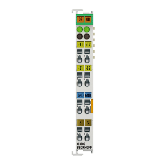
Page 25: Kl3102 - Connection And Led Description
Mounting and wiring KL3102 - Connection and LED description WARNING Risk of injury through electric shock and damage to the device! Bring the Bus Terminal system into a safe, voltage-free state before starting mounting, disassembly or wiring of the Bus Terminals! Fig. 13: KL3102... -
Page 26: Kl3112, Kl3122 - Connection And Led Description
Off: Watchdog timer overflow has occurred. If no process data is transmitted to the Bus Coupler for 100 ms, the green LEDs go out Error LED1 On: Measured current outside the measuring range (> 20 mA) Error LED2 Off: Current in valid range Version: 3.2 KL3102, KL3112, KL3122... -
Page 27: Atex - Special Conditions (Standard Temperature Range)
80°C at the wire branching points, then cables must be selected whose tempera- ture data correspond to the actual measured temperature values! • Observe the permissible ambient temperature range of 0 to 55°C for the use of Beckhoff fieldbus compo- nents standard temperature range in potentially explosive areas! •... -
Page 28: Atex Documentation
Notes about operation of the Beckhoff terminal systems in potentially explosive ar- eas (ATEX) Pay also attention to the continuative documentation Notes about operation of the Beckhoff terminal systems in potentially explosive areas (ATEX) that is available in the download area of the Beckhoff homepage http:\\www.beckhoff.com! Version: 3.2... -
Page 29: Configuration Software Ks2000
Fieldbus Box modules with the aid of which settings can be modified easily. Alternatively, you have full access to all internal registers of the bus couplers and intelligent terminals. Refer to the register description for the meanings of the registers. KL3102, KL3112, KL3122 Version: 3.2... -
Page 30: Sample Program For Kl Register Communication Via Ethercat On Kl3314 Exemplary
This example program (TwinCAT 3) provides change of single register values of the KL3314 as selection of the element type, characteristical settings of the feature register R32 and user scaling offset and gain (R33/ R34) similar as per KS2000. Version: 3.2 KL3102, KL3112, KL3122... -
Page 31: Fig. 16: Settings Of Kl3314 Via Visualisation Of Twincat 3
Preparations for starting the sample programs (tnzip file / TwinCAT 3) • Click on the download button to save the Zip archive locally on your hard disk, then unzip the *.tnzip archive file in a temporary folder. Fig. 17: Opening the *. tnzip archive KL3102, KL3112, KL3122 Version: 3.2... -
Page 32: Fig. 18 Search Of The Existing Hw Configuration For The Ethercat Configuration Of The Example
"Change NetId..." have to be selected. The first 4 numbers of the NetId of the target computer have to be entered; the both last values are 4.1 usually. Example: ◦ NetId of project: myComputer (123.45.67.89.1.1) ◦ Entry via „Change NetId...“: 123.45.67.89.4.1 Version: 3.2 KL3102, KL3112, KL3122... -
Page 33: Access From The User Program
In the BK2000 Lightbus Coupler, the control/status byte is always mapped, in addition to the data bytes. This is always located in the low byte at the offset address of the terminal channel. Fig. 19: Mapping in the Lightbus Coupler - Example for KL3102, KL3112, KL3122 BK3000 Profibus coupler For the BK3000 Profibus coupler, the master configuration should specify for which terminal channels the control and status byte is to be inserted. -
Page 34: Mapping In The Bus Coupler
Access from the user program Fig. 21: Mapping in the Interbus Coupler - Example for KL3102, KL3112, KL3122 Other Bus Couplers and further information Further information about the mapping configuration of Bus Couplers can be found in the Appendix of the respective Bus Coupler manual under Master configuration. -
Page 35: Kl3102, Kl3112, Kl3122
Access from the user program 5.2.1 KL3102, KL3112, KL3122 Default mapping for: CANopen, CANCAL, DeviceNet, ControlNet, Modbus, RS232 and RS485 coupler Conditions Word offset High byte Low byte Complete evaluation: no Ch1 D1 Ch1 D0 Motorola format: no Ch2 D1... -
Page 36: Register Description
• R1 to R5: Reserved • R6: Diagnostic register ◦ High byte: reserved ◦ Low byte: Status byte • R7: Command register High-Byte_Write = function parameter Low-Byte_Write = function number High-Byte_Read = function result Low-Byte_Read = function number Version: 3.2 KL3102, KL3112, KL3122... - Page 37 These registers can only be altered after a code word has been set in R31 [} 38]. • R17: Hardware compensation - offset (B_a) KL3102: [approx. 0x00XX], KL3112 & KL3122 [0xFBxx] 16 bit signed integer*2^-16+1 This register is used for offset compensation of the terminal (Eq. 1.1 [} 14]).
- Page 38 Access from the user program • R18: Hardware compensation - gain (A_a) KL3102: [approx. 0x24XX], KL3112 & KL3122 [0x48xx] 16 bit signed integer*2^-16+1 This register is used for gain compensation of the terminal (Eq. 1.1 [} 14]). 1 corresponds to 0x0000, 2 corresponds to 0xFFFF •...
- Page 39 Fast Fast Step Mode is disabled. Fast Step Mode is active: a fast reaction will follow jumps at the input, in spite of the filter stage being active. In this case the filter is bypassed! KL3102, KL3112, KL3122 Version: 3.2...
- Page 40 Value in R37 Cycle time stop 0x35C0 50 Hz 140 ms 0x2660 70 Hz 100 ms 0x1330 140 Hz 50 ms 0x7FF1 40 ms 0x3FF1 20 ms 0x1001 <4 ms Value in R37 Cycle time limit 0x7FF2 39.6 Hz 40 ms 0x3FF2 77.36 Hz 20 ms 0x1002 158 Hz <4 ms Version: 3.2 KL3102, KL3112, KL3122...
-
Page 41: Control And Status Byte
Bit 3 Bit 2 Limit value 1 not enabled Process data < limit value 1 Process data > limit value 1 Process data = limit value 1 Bit 1 : Overrange Bit 0 : Underrange KL3102, KL3112, KL3122 Version: 3.2... -
Page 42: Register Communication
Example 1: Reading of register 8 in the BK2000 with a KL3102 and the end terminal: If the following bytes are transferred from the controller to the terminal, Version: 3.2... -
Page 43: Examples Of Register Communication
0x1E 0x0C 0x00 0x88 Example 2: Write register 31 in the BK2000 with a KL3102 and the end terminal: If the following bytes (code word [} 38]) are transferred from the controller to the terminal, Byte Byte 3 Byte 2 Byte 1... -
Page 44: Example 2: Writing To An User Register
• The output data word (byte 1 and byte 2) has no meaning during read access. Input Data (answer of the bus terminal) Byte 0: Status byte Byte 1: DataIN1, high byte Byte 2: DataIN1, low byte 0x9F (1001 1111 0x12 0x35 Version: 3.2 KL3102, KL3112, KL3122... - Page 45 • The output data word (byte 1 and byte 2) has no meaning during read access. Input Data (answer of the bus terminal) Byte 0: Status byte Byte 1: DataIN1, high byte Byte 2: DataIN1, low byte 0xA0 (1010 0000 0x00 0x02 Explanation: KL3102, KL3112, KL3122 Version: 3.2...
- Page 46 • The terminal returns a value as a receipt in the status byte that differs only in bit 0.6 from the value of the control byte. • The input data word (byte 1 and byte 2) is of no importance after the write access. Any values still displayed are invalid! Version: 3.2 KL3102, KL3112, KL3122...
-
Page 47: Appendix
Beckhoff's branch offices and representatives Please contact your Beckhoff branch office or representative for local support and service on Beckhoff products! The addresses of Beckhoff's branch offices and representatives round the world can be found on her internet pages: http://www.beckhoff.com You will also find further documentation for Beckhoff components there. - Page 48 Search of the existing HW configuration for the EtherCAT configuration of the example ... Fig. 19 Mapping in the Lightbus Coupler - Example for KL3102, KL3112, KL3122 ........ Fig. 20 Mapping in the Profibus Coupler - Example for KL3102, KL3112, KL3122.........
Need help?
Do you have a question about the KL3102 and is the answer not in the manual?
Questions and answers