Sign In
Upload
Download
Table of Contents
Contents
Add to my manuals
Delete from my manuals
Share
URL of this page:
HTML Link:
Bookmark this page
Add
Manual will be automatically added to "My Manuals"
Print this page
×
Bookmark added
×
Added to my manuals
Manuals
Brands
Beckhoff Manuals
I/O Systems
KL301 Series
Documentation
Beckhoff KL301 Series Documentation
Single- and dual-channel analog input terminals, 0 to 20 ma and 4 to 20 ma
Hide thumbs
1
2
3
4
5
6
7
8
9
10
11
12
13
14
15
16
17
18
19
20
21
22
23
24
25
26
27
28
29
30
31
32
33
34
35
36
37
38
39
40
41
42
43
44
45
46
47
page
of
47
Go
/
47
Contents
Table of Contents
Bookmarks
Table of Contents
Table of Contents
1 Foreword
Notes on the Documentation
Safety Instructions
Documentation Issue Status
2 Product Overview
Kl301X - Introduction
Fig. 1 KL3011, KL3012
Kl302X - Introduction
Fig. 2 KL3021, KL3022
Kl301X, Kl302X - Technical Data
Basic Function Principles
Fig. 3 Kl301X, Kl302X - Data Flow
3 Mounting and Wiring
Instructions for ESD Protection
Installation on Mounting Rails
Fig. 4 Spring Contacts of the Beckhoff I/O Components
Fig. 5 Attaching on Mounting Rail
Fig. 6 Disassembling of Terminal
Fig. 7 Power Contact on Left Side
Installation Instructions for Enhanced Mechanical Load Capacity
Connection
Connection System
Fig. 8 Standard Wiring
Fig. 9 Pluggable Wiring
Wiring
Fig. 11 Connecting a Cable on a Terminal Point
Shielding
Fig. 10 High Density Terminals
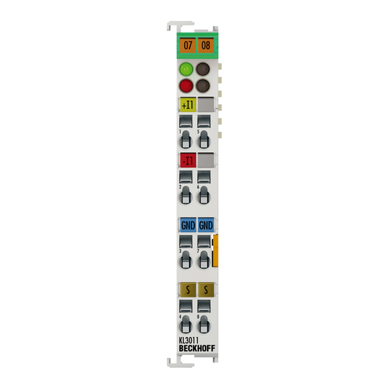
Kl301X - Connection and LED Description
Fig. 12 KL3011, KL3012 - Connection and Leds
Kl302X - Connection and LED Description
Fig. 13 KL3211, KL3022 - Connection and Leds
ATEX - Special Conditions (Standard Temperature Range)
ATEX - Special Conditions (Extended Temperature Range)
ATEX Documentation
4 Configuration Software KS2000
KS2000 - Introduction
Fig. 14 KS2000 Configuration Software
Sample Program for KL Register Communication Via Ethercat on KL3314 Exemplary
Fig. 15: Settings of KL3314 Via Visualisation of Twincat 3
Fig. 16 Opening the *. Tnzip Archive
Fig. 17 Search of the Existing HW Configuration for the Ethercat Configuration of the Example
5 Access from the User Program
Terminal Configuration
Fig. 18 Mapping in the Lightbus Coupler - Example for KL3012 and KL3022
Fig. 19 Mapping in the Profibus Coupler - Example for KL3012 and KL3022
Mapping in the Bus Coupler
KL3011 and KL3021
Fig. 20 Mapping in the Interbus Coupler - Example for KL3012 and KL3022
KL3012 and KL3022
Register Overview
Register Description
Control and Status Byte
Process Data Exchange
Register Communication
Fig. 21 Register Mode Control Byte
Examples of Register Communication
Example 1: Reading the Firmware Version from Register 9
Example 2: Writing to an User Register
6 Appendix
Support and Service
List of Illustrations
Advertisement
Quick Links
Download this manual
Documentation
KL301x, KL302x
Single- and Dual-Channel Analog Input Terminals, 0 to 20 mA
and 4 to 20 mA
Version:
Date:
4.1
2019-02-15
Table of
Contents
Previous
Page
Next
Page
1
2
3
4
5
Advertisement
Chapters
Table of Contents
3
List of Illustrations
47
Table of Contents
Need help?
Do you have a question about the KL301 Series and is the answer not in the manual?
Ask a question
Questions and answers
Related Manuals for Beckhoff KL301 Series
I/O Systems Beckhoff KL3011 Documentation
Single- and dual-channel analog input terminals, 0 to 20 ma and 4 to 20 ma (47 pages)
I/O Systems Beckhoff KL3012 Documentation
Single- and dual-channel analog input terminals, 0 to 20 ma and 4 to 20 ma (47 pages)
I/O Systems Beckhoff KL3021 Documentation
Single- and dual-channel analog input terminals, 0 to 20 ma and 4 to 20 ma (47 pages)
I/O Systems Beckhoff KL3022 Documentation
Single- and dual-channel analog input terminals, 0 to 20 ma and 4 to 20 ma (47 pages)
I/O Systems Beckhoff KL3102 Documentation
Dual-channel analog input terminals,-10 v to +10 v, 0/4 ma to 20 ma (48 pages)
I/O Systems Beckhoff KL3112 Documentation
Dual-channel analog input terminals,-10 v to +10 v, 0/4 ma to 20 ma (48 pages)
I/O Systems Beckhoff KL3122 Documentation
Dual-channel analog input terminals,-10 v to +10 v, 0/4 ma to 20 ma (48 pages)
I/O Systems Beckhoff KL2819 Documentation
Hd bus terminal, 16-channel digital output 24 v dc, with diagnostics (42 pages)
I/O Systems Beckhoff KL1 Series Documentation
Digital input terminals, 24 v dc (52 pages)
I/O Systems Beckhoff EK1101 Documentation
Ethercat bus coupler (85 pages)
I/O Systems Beckhoff EJ18 Series Manual
16-channel digital input modules (47 pages)
I/O Systems Beckhoff EtherCAT EL600x Series Documentation
Serial interface terminals (204 pages)
I/O Systems Beckhoff BK75 series Technical Hardware Documentation
Serial real time communication system. (32 pages)
I/O Systems Beckhoff EL2911 Operating Instructions Manual
Twinsafe potential supply terminal with 4 digital fail-safe inputs (57 pages)
I/O Systems Beckhoff EP4374 Documentation
Ethercat box with analog inputs and outputs (53 pages)
I/O Systems Beckhoff EPI3 Series Documentation
Io-link box modules with analog inputs (98 pages)
This manual is also suitable for:
Kl3011
Kl302 series
Kl3012
Kl3021
Kl3022
Table of Contents
Print
Rename the bookmark
Delete bookmark?
Delete from my manuals?
Login
Sign In
OR
Sign in with Facebook
Sign in with Google
Upload manual
Upload from disk
Upload from URL


Need help?
Do you have a question about the KL301 Series and is the answer not in the manual?
Questions and answers