Sign In
Upload
Download
Table of Contents
Contents
Add to my manuals
Delete from my manuals
Share
URL of this page:
HTML Link:
Bookmark this page
Add
Manual will be automatically added to "My Manuals"
Print this page
×
Bookmark added
×
Added to my manuals
Manuals
Brands
Beckhoff Manuals
I/O Systems
BK75 series
Technical hardware documentation
Beckhoff BK75 series Technical Hardware Documentation
Serial real time communication system.
Hide thumbs
1
Table Of Contents
2
3
4
5
6
7
8
9
10
11
12
13
14
15
16
17
18
19
20
21
22
23
24
25
26
27
28
29
30
31
32
page
of
32
Go
/
32
Contents
Table of Contents
Bookmarks
Table of Contents
Table of Contents
1 Foreword
Notes on the Documentation
Liability Conditions
Delivery Conditions
Copyright
Safety Instructions
State at Delivery
Description of Safety Symbols
2 Basic Information
The Beckhoff Bus Terminal System
The Interfaces
Power Supply
Power Supply to the Power Contacts
Power Contacts
Fieldbus Connection
Configuration Interface
K-Bus Contacts
Supply Isolation
The Operating Modes of the Bus Coupler
Mechanical Construction and Mounting
Electrical Data
The Peripheral Data in the Process Image
Starting Operation and Diagnostics
Terminal Bus Error
Fieldbus Error
Setting the Transmission Rate
Setting the Cable Length
Setting the Station Address
3 SERCOS Interface Coupler BK7500
Introduction to the SERCOS Interface System
The I/O Data Channel
The Transfer Medium: Plugs and Cables
4 Appendix
Example: Composition of a Process Image in the Bus Coupler
The Hardware Configuration
Configuration of the SERCOS Master
5 Index
6 Support and Service
Beckhoff's Branch Offices and Representatives
Beckhoff Headquarters
Advertisement
Quick Links
Download this manual
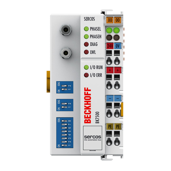
SERCOS Coupler
( Serial Real Time Communication System )
BK7500
Valid for all BK75xx Bus Coupler
Technical Hardware Documentation
Version 1.1
2006-10-30
Table of
Contents
Previous
Page
Next
Page
1
2
3
4
5
Advertisement
Table of Contents
Need help?
Do you have a question about the BK75 series and is the answer not in the manual?
Ask a question
Questions and answers
Related Manuals for Beckhoff BK75 series
I/O Systems Beckhoff SERCOSCoupler BK7500 Technical Hardware Documentation
Serial real time communication system. (32 pages)
I/O Systems Beckhoff EtherCAT EL600x Series Documentation
Serial interface terminals (204 pages)
I/O Systems Beckhoff KL1 Series Documentation
Digital input terminals, 24 v dc (52 pages)
I/O Systems Beckhoff EK1101 Documentation
Ethercat bus coupler (85 pages)
I/O Systems Beckhoff EJ18 Series Manual
16-channel digital input modules (47 pages)
I/O Systems Beckhoff KL301 Series Documentation
Single- and dual-channel analog input terminals, 0 to 20 ma and 4 to 20 ma (47 pages)
I/O Systems Beckhoff EL2911 Operating Instructions Manual
Twinsafe potential supply terminal with 4 digital fail-safe inputs (57 pages)
I/O Systems Beckhoff EP4374 Documentation
Ethercat box with analog inputs and outputs (53 pages)
I/O Systems Beckhoff EPI3 Series Documentation
Io-link box modules with analog inputs (98 pages)
I/O Systems Beckhoff EPP3204-0002 Documentation
4-channel analog input pt100 (rtd) (67 pages)
I/O Systems Beckhoff EPP2 Series Documentation
Ethercat p box modules with digital outputs (153 pages)
I/O Systems Beckhoff KL3102 Documentation
Dual-channel analog input terminals,-10 v to +10 v, 0/4 ma to 20 ma (48 pages)
I/O Systems Beckhoff EPI1 Series Documentation
Io-link box modules with digital inputs (83 pages)
I/O Systems Beckhoff EL3751 Documentation
1-channel multi-functional input for measurement technology (270 pages)
I/O Systems Beckhoff EPI2 Series Documentation
Io-link box modules with digital outputs (94 pages)
This manual is also suitable for:
Sercoscoupler bk7500
Table of Contents
Print
Rename the bookmark
Delete bookmark?
Delete from my manuals?
Login
Sign In
OR
Sign in with Facebook
Sign in with Google
Upload manual
Upload from disk
Upload from URL


Need help?
Do you have a question about the BK75 series and is the answer not in the manual?
Questions and answers