
Related Manuals for Beckhoff KL2819


Summary of Contents for Beckhoff KL2819
- Page 1 Documentation | EN KL2819 HD Bus Terminal, 16-channel digital output 24 V DC, with diagnostics 2022-02-11 | Version: 1.1.0...
-
Page 3: Table Of Contents
Register overview .......................... 32 Register description ......................... 33 Examples of Register Communication .................... 35 6.4.1 Example 1: reading the firmware version from Register 9.......... 35 6.4.2 Example 2: Writing to an user register................ 35 7 Appendix .............................. 39 Support and Service ........................ 39 KL2819 Version: 1.1.0... - Page 4 Table of contents Version: 1.1.0 KL2819...
-
Page 5: Foreword
, XTS and XPlanar are registered trademarks of and licensed by Beckhoff Automation GmbH. Other designations used in this publication may be trademarks whose use by third parties for their own purposes could violate the rights of the owners. Patent Pending... -
Page 6: Safety Instructions
All the components are supplied in particular hardware and software configurations appropriate for the application. Modifications to hardware or software configurations other than those described in the documentation are not permitted, and nullify the liability of Beckhoff Automation GmbH & Co. KG. Personnel qualification This description is only intended for trained specialists in control, automation and drive engineering who are familiar with the applicable national standards. -
Page 7: Documentation Issue Status
• New title page • Update revision status 1.0.0 • First published Firmware and hardware versions Documentation KL2819 Version Firmware Hardware 1.1.0 1.0.0 The firmware and hardware versions (delivery state) can be taken from the serial number printed on the side of the terminal. -
Page 8: Product Overview
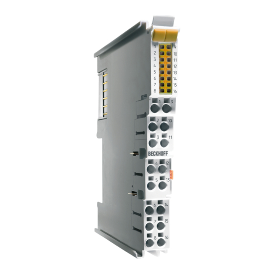
HD Bus Terminal, 16-channel digital output 24 V , 0.5 A, with diagnostics The KL2819 Bus Terminal has 16 digital output channels for the switching of 24 V loads up to 0.5 A. The integrated diagnostics can be evaluated by the controller and indicated by the LEDs. Overtemperature and the lack of a voltage supply to the terminal are supplied as diagnostic information. - Page 9 Output 7 Output 8 Output 8 Output 9 Output 9 Output 10 Output 10 Output 11 Output 11 Output 12 Output 12 Output 13 Output 13 Output 14 Output 14 Output 15 Output 15 Output 16 Output 16 KL2819 Version: 1.1.0...
-
Page 10: Technical Data
Product overview Technical data Technical data KL2819 Connection technology 1-wire Number of Outputs Rated load voltage 24 V (-15 %/+20 %) Current consumption from K-bus typ. 30 mA Load type ohmic, inductive, lamp load Max. output current 0.5 A (short-circuit-proof) per channel Short circuit current <... -
Page 11: Fig. 2 Overload Current Limitation
These are limited by an integrated freewheeling diode to approx. -35 V. Since the current reduces only slowly, a delayed switch-off can occur in many control applications. For example, a valve remains open for many milliseconds. Switch-off times are realized that correspond, for instance, to the switch-on time of the coil. KL2819 Version: 1.1.0... -
Page 12: Fig. 4 Switch-Off Of Inductive Loads
Product overview Fig. 4: Switch-off of inductive loads Version: 1.1.0 KL2819... -
Page 13: Interference-Free Bus Terminals
KL2134 KL2424 KL9110 Terminal name from hardware version EL/ELX terminal EL2004 EL2008 EL2022 EL2024 EL2034 EL2809 EL2828 EL2872 EL2878-0005 EL9110 EL9410 ELX1052 ELX1054 ELX1058 ELX2002 ELX2008 ELX3152 ELX3181 ELX3202 ELX3204 ELX3252 ELX3312 ELX3314 ELX3351 ELX4181 ELX5151 ELX9560 KL2819 Version: 1.1.0... -
Page 14: Fig. 5 Negative Example - Active Load
This can be achieved, for example, through adherence to load-specific standards. ◦ Option 1: Ground feedback and all-pole disconnection The ground connection of the connected load must be fed back to the safely switched ground. Version: 1.1.0 KL2819... -
Page 15: Fig. 6 Ground Connection Of The Load: Correct (K1) And Incorrect (K2)
If solution option 1 is not feasible, the ground feedback and all-pole disconnection can be dispensed with if the danger of feedback due to a cable short-circuit can be excluded by other measures. These measures, which can be implemented alternatively, are described in the following sections. KL2819 Version: 1.1.0... -
Page 16: Fig. 7 Short Circuit Fault Exclusion Through Protected Cable Laying
Summary of safety classifications Feedback avoidance measures DIN EN ISO 13849-1 IEC 61508 EN 62061 Fault exclusion max. max. SIL3 max. SIL2 * Cable short-circuit Cat. 4 Ground feedback and all-pole max. SIL3 disconnection Version: 1.1.0 KL2819... -
Page 17: Mounting And Wiring
• Surroundings (working place, packaging and personnel) should by grounded probably, when handling with the devices. • Each assembly must be terminated at the right hand end with a KL9010 bus end terminal, to ensure the protection class and ESD protection. Fig. 8: Spring contacts of the Beckhoff I/O components KL2819 Version: 1.1.0... -
Page 18: Installation On Mounting Rails
To mount the mounting rails with a height of 7.5 mm under the terminals and couplers, you should use flat mounting connections (e.g. countersunk screws or blind rivets). Version: 1.1.0 KL2819... -
Page 19: Fig. 10 Disassembling Of Terminal
EL91xx, EL92xx) interrupt the power contacts and thus represent the start of a new supply rail. PE power contact The power contact labeled PE can be used as a protective earth. For safety reasons this contact mates first when plugging together, and can ground short-circuit currents of up to 125 A. KL2819 Version: 1.1.0... -
Page 20: Fig. 11 Power Contact On Left Side
Power Feed Terminals can be released and pulled at least 10 mm from the group of terminals. WARNING Risk of electric shock! The PE power contact must not be used for other potentials! Version: 1.1.0 KL2819... -
Page 21: Connection
Insert the new component and plug in the connector with the wiring. This reduces the installation time and eliminates the risk of wires being mixed up. The familiar dimensions of the terminal only had to be changed slightly. The new connector adds about 3 mm. The maximum height of the terminal remains unchanged. KL2819 Version: 1.1.0... -
Page 22: Fig. 14 High Density Terminals
Ultrasonically “bonded” (ultrasonically welded) conductors Ultrasonically “bonded” conductors It is also possible to connect the Standard and High Density Terminals with ultrasonically “bonded” (ultrasonically welded) conductors. In this case, please note the tables concerning the wire-size width [} 23]! Version: 1.1.0 KL2819... -
Page 23: Wiring
The cables are released, as usual, using the contact release with the aid of a screwdriver. See the following table for the suitable wire size width. KL2819 Version: 1.1.0... -
Page 24: Shielding
EL/KL terminals to face forward (see Fig. Recommended distances for standard installation position). The terminals are ventilated from below, which enables optimum cooling of the electronics through convection. “From below” is relative to the acceleration of gravity. Version: 1.1.0 KL2819... -
Page 25: Fig. 16 Recommended Distances For Standard Installation Position
Other installation positions All other installation positions are characterized by different spatial arrangement of the mounting rail - see Fig Other installation positions. The minimum distances to ambient specified above also apply to these installation positions. KL2819 Version: 1.1.0... -
Page 26: Disposal
Products marked with a crossed-out wheeled bin shall not be discarded with the normal waste stream. The device is considered as waste electrical and electronic equipment. The national regulations for the disposal of waste electrical and electronic equipment must be observed. Version: 1.1.0 KL2819... -
Page 27: Ks2000 Configuration Software
Fieldbus Box modules with the aid of which settings can be modified easily. Alternatively, you have full access to all internal registers of the bus couplers and intelligent terminals. Refer to the register description for the meanings of the registers. KL2819 Version: 1.1.0... -
Page 28: Parameterization With Ks2000
Click on the Login button. The configuration software will now load the information for the connected fieldbus station. In the sample shown, this is • a CX5020 Embedded PC • a KL2819 HD bus terminal • a KL9010 bus end terminal Fig. 19: Display of the fieldbus station in KS2000 Version: 1.1.0... -
Page 29: Fig. 20 Ks2000 Tree Branches For Channel 1 Of The Kl2819
Fig. 20: KS2000 tree branches for channel 1 of the KL2819 For the KL2819, the branches Register, Settings and ProcData are displayed: • Register [} 30] permits direct access to the registers of the KL2819. • ProcData displays the KL2819 process data. -
Page 30: Register
KS2000 Configuration software Register You can access the registers of the KL2819 directly under Register.– The meaning of the register is explained in the register overview. Fig. 21: Register view in KS2000 Version: 1.1.0 KL2819... -
Page 31: Access From The User Programm
: Write access CB.5 to Reg. no. Register number: CB.0 Enter here the number of the register that you wish - to read with input data word DataIN, or - to write with output data word DataOUT. KL2819 Version: 1.1.0... -
Page 32: Register Overview
0x0000 R31 [} 34] Code word register 0x0000 R32 [} 34] Feature register 0x001F SEEPROM R33 [} 34] Activated Channel Diagnostic Register 0xFFFF 65535 SEEPROM R34 [} 34] Watchdog Channel Outputs Register 0x0000 SEEPROM reserved 0x0000 … … reserved 0x0000 Version: 1.1.0 KL2819... -
Page 33: Register Description
All registers can be read or written via register communication [} 35]. They are used for the parameterization of the terminal. R8: Terminal description Register R8 contains the designation of the KL2819 terminal: 0x0B03 (2819 R9: Firmware version Register R9 contains the ASCII coding of the terminal's firmware version, e.g. 0x3141 (1A) . - Page 34 R34.3 R34.2 R34.1 R34.0 Name Definition Definition Definition Definition Definition Definition Definition Definition output output output output output output output output Channel 8 Channel 7 Channel 6 Channel 5 Channel 4 Channel 3 Channel 2 Channel 1 Version: 1.1.0 KL2819...
-
Page 35: Examples Of Register Communication
0xDF (1101 1111 0x12 0x35 Explanation: • Bit 0.7 set means: Register communication switched on. • Bit 0.6 set means: writing to the register. • Bits 0.5 to 0.0 specify the register number 31 with 01 1111 KL2819 Version: 1.1.0... - Page 36 • Bit 0.6 set means: writing to the register. • Bits 0.5 to 0.0 indicate register number 32 with 10 0000 • The output data word (byte 1 and byte 2) contains the new value for the feature register. Version: 1.1.0 KL2819...
- Page 37 • Bit 0.6 set means: writing to the register. • Bits 0.5 to 0.0 specify the register number 31 with 01 1111 • The output data word (byte 1 and byte 2) contains 0x0000 for reactivating write protection. KL2819 Version: 1.1.0...
- Page 38 • The terminal returns a value as a receipt in the status byte that differs only in bit 0.6 from the value of the control byte. • The input data word (byte 1 and byte 2) is of no importance after the write access. Any values still displayed are invalid! Version: 1.1.0 KL2819...
-
Page 39: Appendix
Please contact your Beckhoff branch office or representative for local support and service on Beckhoff products! The addresses of Beckhoff's branch offices and representatives round the world can be found on her internet pages: https://www.beckhoff.com You will also find further documentation for Beckhoff components there. - Page 40 Fig. 17 Other installation positions ......................Fig. 18 KS2000 configuration software....................Fig. 19 Display of the fieldbus station in KS2000 ..................Fig. 20 KS2000 tree branches for channel 1 of the KL2819..............Fig. 21 Register view in KS2000......................Version: 1.1.0 KL2819...
- Page 42 More Information: www.beckhoff.com/KL2819 Beckhoff Automation GmbH & Co. KG Hülshorstweg 20 33415 Verl Germany Phone: +49 5246 9630 info@beckhoff.com www.beckhoff.com...
Need help?
Do you have a question about the KL2819 and is the answer not in the manual?
Questions and answers