
Subscribe to Our Youtube Channel
Related Manuals for Afag UG 20 Series


Summary of Contents for Afag UG 20 Series
- Page 1 Universal Gripper UG 20, UG 25 - Declaration of Incorporation - Module Information - Montage Instructions - Maintenance Instructions „Translation“ of the Original Montage Instructions © copyright by Afag Automation AG...
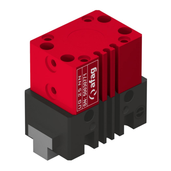
- Page 2 These Montage Instructions apply to: Type Order No. Type Order No. UG 20 NN 50032661 UG 25 NN 50030771 UG 20 NC 50032663 UG 25 NC 50030772 UG 20 NO 50032664 UG 25 NO 50030773 Version of this documentation: UG 20-UG 25-OI-vers. 3.2 gb. 06.08.14.doc Symbols: Assembly and initial start-up must be carried out by qualified personnel only...
-
Page 3: Table Of Contents
Table of Contents: 1.0.0 Declaration of Incorporation Page 4 1.1.0 Declaration of Incorporation according to the Machinery Directive 2006/42/EG 2.0.0 Module Information Page 5 2.1.0 Transport and storage (packing and unpacking) Page 5 2.1.1 Assembly for the gripper Page 6 2.1.2 Mounting for the gripper fingers Page 6 2.1.3 Hole matrix and centering bushings... - Page 4 Directive 2006/42/EC, where appropriate. Name and address of the person authorised to compile the relevant technical documentation: Lanz Beat, PM & Marketing-Services, Afag Automation AG Place, Date: Huttwil, 06.02.2013 Siegfried Egli...
-
Page 5: Module Information
2.0.0 Module Information 2.1.0 Transport and storage (packing and unpacking) CAUTION The UG Universal gripper is packed in the original cardboard box; if the module is not handled properly it may fall out of the box when unpacking and cause injuries to limbs or squeeze your fingers. -
Page 6: Assembly For The Gripper
2.1.1 Assembly for the gripper Depending on the application the gripper can be attached from the side or from below: Installation from below Installation from the side Use the centering bushings included in the scope of supply to determine the position. 2.1.2 Mounting for the gripper finger NOTE Further elements to be mounted can be attached to the fastening... -
Page 7: Hole Matrix And Centering Bushings
2.1.3 Hole matrix and centering bushings Hole matrix at the UG 20 / UG 25 Universal gripper UG 20 UG 25 Hole matrix 20x20mm Hole matrix 30x30mm Thread / bore hole Thread/bore hole Centering Ø 5x2.5mm Centering Ø 7x3mm bushings (H7) bushings Use the centering bushings included in the scope of supply for positioning and insert these sleeves in the diagonally opposite bore holes of the mounting grid. -
Page 8: Tightening Torques For Bolts
Modifications on the UG Universal gripper that are not described in these Montage Instructions or have not been approved in writing by Afag Automation AG are not permitted. In case of improper changes or assembly, installation, operation and maintenance or repairs Afag rejects all liability. -
Page 9: Montage Instructions
Directive 206/42/EG, where appropriate. Name and address of the person authorised to compile the relevant technical documentation: Lanz Beat, PM & Marketing-Services, Afag Automation AG UG 20-UG 25-OI-vers. 3.2 gb. 06.08.14.doc... -
Page 10: Symbols
The UG 20/25 Universal gripper can be installed in the horizontal or vertical position. Modifications on the UG 20/25 Universal gripper that are not described in these Montage Instructions or have not been approved in writing by Afag Automation AG are not permitted. In case of improper changes or assembly, installation, operation, maintenance or repairs, Afag Automation AG rejects all liability. -
Page 11: General Description For The Module
3.1.3 General description for the module UG 20 / UG 25 Cylinder casing Cover of fastening screws Jaw casing Side mounting holes Grip jaws Top Mounting holes C-grooves for magnetic sensors Fastening thread of holding-down device Holder for inductive sensors Cover plate of grip mechanism Set screws of stroke detection Pneumatic connections... -
Page 12: Scope Of Supply
Modifications on the module that are not described in these Montage Instructions or have not been approved in writing by Afag are not permitted. In case of improper changes or assembly, installation, operation, maintenance or repairs, Afag rejects all liability. -
Page 13: Guarantee
Afag parts. *whichever comes first When repairs are carried out by the customer without prior training or instruction by Afag automation AG the warranty will become void. Any additional claims are excluded. 3.1.7 Areas of application The UG 20/25 are exclusively designed for the gripper movement of load capacities of up to UG 20 gripping forces open178 N (closed 150 N);... -
Page 14: Dimensions Drawing Ug
3.1.8 Dimensions drawing UG 20 UG 20-UG 25-OI-vers. 3.2 gb. 06.08.14.doc... -
Page 15: Technical Data Of The Ug
3.1.9 Technical data of the UG 20 UG 20-UG 25-OI-vers. 3.2 gb. 06.08.14.doc... -
Page 16: Preferred Combinations Ug
3.2.0 Preferred combinations UG 20 UG 20-UG 25-OI-vers. 3.2 gb. 06.08.14.doc... -
Page 17: Dimensions Drawing Ug
3.2.1 Dimensions drawing UG 25 UG 20-UG 25-OI-vers. 3.2 gb. 06.08.14.doc... -
Page 18: Technical Data Of The Ug
3.2.2 Technical data of the UG 25 UG 20-UG 25-OI-vers. 3.2 gb. 06.08.14.doc... -
Page 19: Preferred Combinations Ug
3.2.3 Preferred combinations UG 25 UG 20-UG 25-OI-vers. 3.2 gb. 06.08.14.doc... - Page 20 3.2.4 Pneumatic connection for the UG-Universal gripper NOTE Minimal compressed air quality according to ISO 8573-1; 2010 (7-4-4) “Close” connection “Open” connection Compressed air connection One-way restrictor Maintenance unit Gripper (UG 20 /UG 25) Prise d’air 5-2 port directional control valve P1/P2 UG 20-UG 25-OI-vers.
-
Page 21: Preparation For Commissioning
3.2.5 Preparation for Commissioning Attach the sensors used by you and align them roughly when they are not under pressure. Setting the Inductive Sensors Remove the cover (1) Loosen the fastening screw under the cover (slot-head screwdriver, size 00) ... -
Page 22: Fitting The Proximity Switch In The Module Groove
3.2.7 Fitting the proximity switch in the module grooves In Front stand in the UG 20 / UG 25 C-grooves for the admission of the sensors at the possession. With two proximity switch open or closing position questioned. Proximity Switch Screw for fastening the clamping Piece in the groove Screw for fastening the proximity... -
Page 23: Example Of Application Of Sensor Technology Combined With
3.2.8 Example of application of sensor technology combined with specially formed grip fingers (depending on application): Position of grippers Description Gripper closed The grip fingers (1) contact each other. This position is usually queried by a magnetic sensor. Part (2) correctly gripped Depending on size and form of the part this position is queried by magnetic or inductive sensors. -
Page 24: Maintenance Instruction
4.0.0 Maintenance instructions 4.1.0 Maintenance and servicing of the UG 20/25 Universal gripper CAUTION The module may only be disassembled when the system is aerated and deactivated. If pneumatic connections are disconnected when they are under pressure, this may result in serious personal injury due to fast movements of moving parts. -
Page 25: Servicing
Open guides and piston rods should be covered with a grease layer to avoid formation of rust. Recommendation: Clean and grease once a month! Afag standard: - Staburax NBU8EP (flat guides) - Blasolube 301 (piston rods) UG 20-UG 25-OI-vers. 3.2 gb. 06.08.14.doc... -
Page 26: Accessories For The Ug 20 / Ug
4.1.2 Accessories the UG 20 / UG 25 The accessories find in the catalog technical and on WEB: www.afag.com Types Order No. Centering bushings 7x3 11016850 INI c10x28.5-Em-PNP-close-M8x1 50033432 INI c10x9-Em-PNP-NO-M8x1 50313986 INI Ø4x25-Sn1.0-PNP-close-M8x1 11016714 INI Ø4x25-Sn1.0-PNP-NC-M8x1 50093507 INI c10x19.5-Em-PNP-NO-M8x1 50313987 4.1.3 Trouble-shooting... -
Page 27: Disassembly And Repair
4.1.4 Disassembly and repair When the module is damaged it can be returned to Afag Automation AG for repair. CAUTION The module may only be disassembled when the system is aerated and deactivated. If pneumatic connections are disconnected when they are under pressure, this may result in serious personal injury due to fast movements of moving parts. - Page 28 Afag Automation AG Fiechtenstrasse 32 4950 Huttwil Switzerland +41 (0)62 – 959 86 86 Tel.: +41 (0)62 – 959 87 87 Fax.: e-mail: sales@afag.com Internet: www.afag.com...
Need help?
Do you have a question about the UG 20 Series and is the answer not in the manual?
Questions and answers