
Related Manuals for Afag PS 25/50


Summary of Contents for Afag PS 25/50
- Page 1 High precision slide PS 25 /32 and ZA - Declaration of Incorporation - Module Information - Montage Instructions - Maintenance Instructions „Translation“ of the Original Montage Instruction © Copyright by Afag Automation AG...
- Page 2 These Montage Instructions apply to: Type Order No. Type Order No. PS 25/50 50076883 PS 32/150 50076907 PS 25/100 50076888 PS 32/200 50076909 PS 25/150 50076891 PS 32/250 50076911 PS 25/200 50076893 PS 32/300 50076913 PS 32/50 50076902 PS 32/100...
-
Page 3: Table Of Contents
Table of Contents: 1.0.0 Declaration of Incorporation Page 5 1.1.0 Declaration of Incorporation according to the Machinery Directive 2006/42/EG Page 5 2.0.0 Module Information Page 6 2.1.0 Transport and storage (packing and unpacking) Page 6 2.1.1 Possibilities of fastening the Ps 25/32 Page 7 2.1.2 Hole matrix and centering bushings Page 8... - Page 4 3.2.9 Mounting the stopper angle Page 29 3.3.0 Mounting procedure for the ZA-intermediate stop Page 29 3.3.1 Adjustment of the stop screw with shock absorber Page 34 3.3.2 Operating sequence of the intermediate position with axial interm. stop Page 35 4.0.0 Maintenance Instructions Page 37 4.1.0 Maintenance and servicing of the PS 25/32...
-
Page 5: Directive 2006/42/Eg
Directive 2006/42/EC, where appropriate. Name and address of the person authorised to compile the relevant technical documentation: Lanz Beat, PM & Marketing-Services, Afag Automation AG Place, Date: Huttwil, 21. Juli 2014 Sigfried Egli... -
Page 6: Module Information
2.0.0 Module Information 2.1.0 Transport and storage (packing and unpacking) CAUTION The PS module is packed in the original cardboard boxe, if the module is not handled properly it may fall out of the box when unpacking and cause injuries to limbs or squeeze your fingers. NOTE Consider please! With each module security is settled a technical newspaper. -
Page 7: Possibilities Of Fastening The Ps
2.1.1 Possibilities of fastening the PS 25/32 Depending on the application either the base body or the slide can be mounted rigidly. Installation of base body from below Mounting of gantry model Use the centering bushings included in the scope of supply to determine the position and insert these bushings in the opposite borings of the mounting grid. -
Page 8: Hole Matrix And Centering Bushings
2.1.2 Hole matrix and centering bushings Hole matrix at the PS 25/32 High precisions slide PS 25/PS32 Hole matrix 48x48 mm (30x30 mm) Thead / bore hole (M4) Centering Ø 9x4 mm (Ø 7x3 mm) bushings (H7) Use the centering bushings included in the scope of supply for positioning and insert these centering bushings in the diagonally opposite bore holes of the mounting grid. -
Page 9: Tightening Torques For Bolts
Safety instructions Modifications on the PS 25/32 module that are not described in these Montage Instructions or have not been approved in writing by Afag Automation AG are not permitted. In case of improper changes or assembly, installation, operation and maintenance or repairs Afag rejects all liability. -
Page 10: Slide Unit Load Factors Ps
2.1.4 Slide unit load factors PS 25 PS 25-32-OI-vers. 3.5 gb.21.07.14.docx... -
Page 11: Preferred Combinaisons Ps
2.1.5 Preferred combinations PS 25 PS 25-32-OI-vers.3.5 gb. 21.07.14.docx... -
Page 12: Slide Unit Load Factors Ps
2.1.6 Slide unit load factors PS 32 PS 25-32-OI-vers. 3.5 gb.21.07.14.docx... -
Page 13: Preferred Combinations Ps
2.1.7 Preferred combinations PS 32 PS 25-32-OI-vers.3.5 gb. 21.07.14.docx... -
Page 14: Montage Instructions
3.0.0 Montage Instructions 3.1.0 These Montage Instructions are valid for: Product name: High precision slide (pneumatic) Types: PS 25/50; PS 25/100; PS 25/150; PS 25/200 PS 32/50; PS 32/100; PS 32/150; PS 32/200; PS 32/250; PS 32/300 Sequential series No. 50xxxxxx... -
Page 15: Symbols
The PS 25/32 High precision slide can be installed in the horizontal or vertical position. Modifications on the PS 25/32 High precision slide that are not described in these Montage Instructions or have not been approved in writing by Afag Automation AG are not permitted. In case of improper changes or assembly, installation, operation, maintenance or repairs, Afag Automation AG rejects all liability. -
Page 16: Description Of The Module
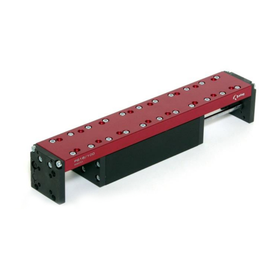
3.1.3 Description of the module Body base Counterpart (IProximity switch) Slids Shock absorber Proximity switch holder Counterpart (Shock absorber) Adjusting stop screw The PS 25/32 consists of the base body (1) with pneumatic connections and cylinder and the slide (2). The limit positions are set by a proximity switch holder (3) and the corresponding counterpart (8). -
Page 17: Scope Of Supply
Modifications on the module that are not described in these Montage Instructions or have not been approved in writing by Afag are not permitted. In case of inexpert changes or improper assembly, installation, operation, maintenance or repairs, Afag rejects all liability. -
Page 18: Warranty
Afag AG. *First go in event When repairs are carried out by the customer without prior training or instruction by Afag automation AG the warranty will become void. No additional claims can be entertained. 3.1.7 Areas of application The PS 25/32 High precision slides are exclusively designed for the linear movement of load capacities of up to 10 –... -
Page 19: Dimensions Drawing Ps
3.1.8 Dimensions drawing PS 25 PS 25-32-OI-vers.3.5 gb. 21.07.14.docx... -
Page 20: Technical Data Of The Ps
3.1.9 Technical data of the PS 25 PS 25-32-OI-vers. 3.5 gb.21.07.14.docx... -
Page 21: Dimensions Drawing Ps
3.2.0 Dimensions drawing PS 32 PS 25-32-OI-vers.3.5 gb. 21.07.14.docx... -
Page 22: Technical Data Ps
3.2.1 Technical data of the PS 32 PS 25-32-OI-vers. 3.5 gb.21.07.14.docx... - Page 23 3.2.2 Technical data of the PS 32 PS 25-32-OI-vers.3.5 gb. 21.07.14.docx...
-
Page 24: Pneumatic Connection
3.2.3 Pneumatic connection PS Module The pneumatic connection PS 25 = M5; (PS 32 = G 1/8“) are located on the left and right side of the base body. Pneumatic connections that are not used must be closed airtight with the locking screws included in the scope of supply. Compressed air connection One-way restrictor Maintenance unit... -
Page 25: Preparation For Start-Up
3.2.4 Preparation for start-up Before commissioning the shock absorber with stopper and the initiator holder must be set in such a way that the stroke provided is attenuated correctly. Commissioning Ventilate the total system slowly. Note the permissible values (see catalogue) regarding: useful load motion frequency moment loads on the guide system... -
Page 26: Setting The Shock Absorbers And The Stop Screw
3.2.5 Setting the shock absorbers and the stop screw Inside installation Outside installation (by strocke100 mm) The sensor holder is pulled along when the shock absorber is adjust Sensor is fastened to the circumference by means of a tensioning nut (no grub screw) Fine adjustment of the shock absorber via Shock absorber and sensor... -
Page 27: Inquiry Of The Sensors
3.2.6 Inquiry of the sensor Clamping proximity switches are used to query the PS 25/32 stop positions. Polling of the stop positions is monitored by an LED on the initiator. If the LED switch status does not change during inquiry of the stop positions the sensor is faulty and must be replaced. - Page 28 3.2.8 Optional module with intermediate stop ZA-PS The precision slides PS 25 / 32 can be retrofitted with the ZA-PS 25 / 32. The ZA intermediate positions for the PS modules distinguish themselves through their compact size and their design which is adapted to the module. This intermediate stop can be fitted onto the slide plate for extending and retracting depending on the module stroke length.
- Page 29 Typ: ZA-PS 25 ZA-PS 32 Order No. 50222737 50222738 Weight of module: 0,9 kg 1,4 kg Operating Pressure: 4-8 bar 4-8 bar Air connect Damping traverse: Hydr. Hydr. Included in the delivery scope: ZA module with fastening screws Example: ZA Stopper angle plate with shock absorber, stop screw and fastening screws Mounting ZA on the PS module (effective for the extension stroke)
-
Page 30: Mounting The Stopper Angle
3.2.9 Mounting the stopper angle Undo the 4 Torx screw at the front (rear) base body plate, as these threaded holes are required for mounting the stopper angle! Stopper angle with accessories Adjusting stop screw Shock absorber Fixing screw 3.3.0 Mounting procedure for the ZA intermediate stop (effective for the extension stroke) Determine the intermediate position on the module slide plate Fasten the ZA with screws on the module slide plate... - Page 31 The stopper angle of contact Insert the 4 allen screw for the stopper angle included in the accessories and tighten screw. ZA-shock absorber and stop screw Turn shock absorber and stop screw through 180° so that they act on the catch of the intermediate stop.
-
Page 32: Adjustment Of The Stop Screw With Shock Absorber
3.3.1 Fine adjustment of the stop screw with shock absorber Range of adjustment for shock absorber and stop screw 20 mm (PS 25/32) Rotating the ZA cylinder (Air connection upside) Undo the 4 screws at the cylinder and pull cylinder backward until it can rotated through 180°. - Page 33 This application is not permitted CAUTION The ZA intermediate stop must not be mounted in such a way that the ZA catch on the module slide moves away from the base body. In the case of a failure of the shock absorber the screws would be overloaded after some 10‘000 cycles and would break.
- Page 34 Stop position on the intermediate stop Example: ZA 25 Position of the intermediate stop on the ZA catch Final position with retracted ZA catch PS 25-32-OI-vers. 3.5 gb.21.07.14.docx...
-
Page 35: Operating Sequence Of The Intermediate Position With Axial Interm
3.3.2 Operating sequence of the intermediate position with axial intermediate Stop cylinder mounted on right-hand side. 1. Pressure on P1 (left module) and pressure on P3 (rear intermediate position cylinder) 2. Pressure on P2 (module moves to the right) and pressure on P3 (rear intermediate position cylinder) 3. - Page 36 Set stop position with extension to Module PS Stop position with extension Procedure: Disconnect compressed air from module, loosen and remove the two stop pins (1), screw in and tighten new stop pins. PS 25-32-OI-vers. 3.5 gb.21.07.14.docx...
-
Page 37: Maintenance Instructions
4.0.0 Maintenance instructions 4.1.0 Maintenance and servicing of the PS 25/32 High-precision slide CAUTION The module may only be disassembled when the system is aerated and deactivated. If pneumatic connections are disconnected when they are under pressure, this may result in serious personal injury due to fast movements of moving parts. -
Page 38: Servicing
Open guides and piston rods should be covered with a grease layer to avoid formation of rust. Recommendation: Clean and grease once a month! Afag standard: - Staburax NBU8EP (flat guides) - Blasolube 301 (piston rods) PS 25-32-OI-vers. 3.5 gb.21.07.14.docx... - Page 39 INI Ø 4X25-Sn1.0-PNP-close-M8x1 11016714 INI Ø 4/6.5x45-Sn1.0-PNP-close-M8x1 11009034 *Intermediate position ZA (Position 2) 50100321 *Intermediate position ZA (Position 4) 50100325 * see cataloge technical NOTE They find other accessories in the technical catalogue or in the WEB. www.afag.com PS 25-32-OI-vers.3.5 gb. 21.07.14.docx...
-
Page 40: Trouble-Shooting
Increase pressure to max. 8 bar position Module wrongly connected Check pneumatic connection One-way restrictor completely Open one-way restrictor closed Module defective Return module to Afag Slide moves too Shock absorber wrongly Readjust shock absorber hard to the final adjusted position Replace shock absorber Shock absorber faulty Max. -
Page 41: Disassembly And Repair
4.1.4 Disassembly and repair When the module is damaged it can be returned to Afag automation AG for repair. CAUTION The module may only be disassembled when the system is aerated and deactivated. If pneumatic connections are disconnected when they are under pressure, this may result in serious personal injury due to fast movements of moving parts. -
Page 42: Disposal
4.1.5 Expendable parts PS 25 PS 32 Types Order No. Order No. Shock absorber ASSD M12x1-1; (ASSD 50105234 (50105235) M14x1-1) Clamping support SD 50138588 (50138595) Screw clamping support M4x12 50189496 (50189496) Clamping support the proximity switch 50138590 (50138597) Initiator holder incl. spring pliers 6Kt. Mu. 50138579 (50138592) Shock attachment... - Page 43 PS 25-32-OI-vers.3.5 gb. 21.07.14.docx...
- Page 44 Afag Automation AG Fiechtenstrasse 32 CH - 4950 Huttwil Switzerland Tel.: +41 (0)62 959 86 86 Fax.: +41 (0)62 959 87 87 e-mail: sales@afag.com Internet: www.afag.com PS 25-32-OI-vers. 3.5 gb.21.07.14.docx...
Need help?
Do you have a question about the PS 25/50 and is the answer not in the manual?
Questions and answers