Chapters
Table of Contents

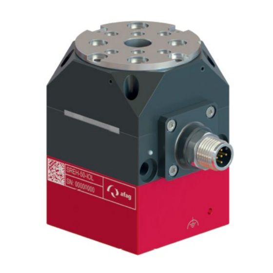
Related Manuals for Afag SREH-50-IOL


Summary of Contents for Afag SREH-50-IOL
- Page 1 Assembly and operating instructions Electric Smart Rotary Module SREH-50-IOL Translation of the Original Assembly Instructions EN SREH-50-IOL Order no.: 50503985 Assembly instructions EN SREH-50-IOL Date 17.06.2022 Version 1.0 1–52 ...
- Page 2 Your Afag team © Subject to modifications The modules have been designed by Afag Automation AG according to the state of the art. Due to the constant technical development and improvement of our products, we reserve the right to make technical changes at any time.
-
Page 3: Table Of Contents
2.8.3 Dangers due to magnetic fields (effects on medical implants) .... 13 2.8.4 Danger due to high temperatures ............13 2.8.5 Mechanical hazards ................13 Technical data ...................... 14 Dimensional drawing SREH-50-IOL ............14 Technical data SREH-50-IOL ..............15 Preferred combinations SREH-50-IOL ............16 Module loads ....................17 Positioning time .................. - Page 4 Decommissioning, disassembly, disposal ............45 10.1 Safety instructions for decommissioning and disposal ....... 45 10.2 Decommissioning ..................45 10.3 Disposal ...................... 45 Declaration of incorporation ................46 4 – 52 Assembly instructions EN SREH-50-IOL Date 17.06.2022 Version 1.0 ...
-
Page 5: General
NOTICE This safety note points out a potentially dangerous situation which, if not avoided, can cause substantial damage to property and the environment. Assembly instructions EN SREH-50-IOL Date 17.06.2022 Version 1.0 5–52 ... -
Page 6: Additional Symbols
In these assembly instructions the following symbols are used to highlight instructions, results, references, etc. Symbol Description Instructions (steps ...) Results of actions References to sections Enumerations not ordered 6 – 52 Assembly instructions EN SREH-50-IOL Date 17.06.2022 Version 1.0 ... -
Page 7: Applicable Documents
This does also apply to defective accessories and wear parts. Normal wear and tear are excluded from the warranty. The warranty covers the replacement or repair of defective Afag parts. Further claims are excluded. The warranty shall expire in the following cases: ... -
Page 8: Safety Instructions
Any use other than or beyond the intended use described above is considered a misuse of the smart rotary module. Especially the following use is considered a misuse: Use in potentially explosive atmospheres 8 – 52 Assembly instructions EN SREH-50-IOL Date 17.06.2022 Version 1.0 ... -
Page 9: Obligations Of The Operator And The Personnel
the operating company shall be solely responsible for such damage, and Afag does not accept any liability for damage caused by improper use. 2.4 Obligations of the operator and the personnel 2.4.1... -
Page 10: Obligations Of The Personnel
Authorized persons who due to their specialized professional training, expertise and experience can identify risks and preventing possible hazards arising from the use of the device. 10 – 52 Assembly instructions EN SREH-50-IOL Date 17.06.2022 Version 1.0 ... -
Page 11: Personal Protective Equipment (Ppe)
2.7 Changes and modifications No changes may be made to the module which have not been described in these assembly instructions or approved in writing by Afag Automation AG. Afag Automation AG accepts no liability for unauthorised changes or improper assembly, installation, commissioning, maintenance or repair work. -
Page 12: General Hazards / Residual Risks
When connecting and operating the module, unexpected movements can cause personal injury or damage to property. Only qualified personnel may work with or on the module. 12 – 52 Assembly instructions EN SREH-50-IOL Date 17.06.2022 Version 1.0 ... -
Page 13: Danger Due To Electricity
Limbs can be crushed by moving components! Work on and with the module may only be carried out by qualified personnel. Never reach into the system during normal operation! Assembly instructions EN SREH-50-IOL Date 17.06.2022 Version 1.0 13–52 ... -
Page 14: Technical Data
Technical data Technical data 3.1 Dimensional drawing SREH-50-IOL Fig. 1 Dimensional drawing smart rotary module SREH-50-IOL 14 – 52 Assembly instructions EN SREH-50-IOL Date 17.06.2022 Version 1.0 ... -
Page 15: Technical Data Sreh-50-Iol
Technical data 3.2 Technical data SREH-50-IOL Equipped with H1 lubricant food grade lubricant. Assembly instructions EN SREH-50-IOL Date 17.06.2022 Version 1.0 15–52 ... -
Page 16: Preferred Combinations Sreh-50-Iol
Technical data 3.3 Preferred combinations SREH-50-IOL 16 – 52 Assembly instructions EN SREH-50-IOL Date 17.06.2022 Version 1.0 ... -
Page 17: Module Loads
0ms and the positioning time thus corresponds to the travel time. The precise swivel time calculation can be determined via the online engineering tool Afag PerfectCycle ➡ www.perfectcycle.afag.com. Assembly instructions EN SREH-50-IOL Date 17.06.2022 Version 1.0... -
Page 18: Transport, Packaging And Storage
This information sheet must be read by every person who carries out work with and on the module! Fig. 2 Scope of delivery smart rotary module [Unt] SREH-50-IOL Smart rotary module (weight 0.6 kg) Centring sleeve Ø8x3.5 Fastening screws M5x55 mm Rotation limitation SREH-50... -
Page 19: Transport
4.4 Packaging The smart rotary module is transported in the Afag Automation AG transport packaging. If no Afag packaging is used, the smart rotary module must be packed in such a way that it is protected against shocks and dust. -
Page 20: Design And Description
4. FE connection thread M3x6 mm 8. Output flange 5.2 Product description The SREH-50-IOL module is a highly compact electric smart rotary module for rotating payloads. The controller integrated in the rotary module is controlled via a 5-pole IO-Link and is equipped with two separate, galvanically isolated supplies - one supply each for the logic and one for the motor. -
Page 21: Accessories
Sensor actuator cable-S4-1.5m-90-0-2 50573864 Sensor actuator cable-S4-3m-0-0-2 50573865 Sensor actuator cable-S4-3m-90-0-2 50573866 Sensor actuator cable-S4-5m-0-open-2 50573867 Sensor actuator cable-S4-5m-90-open-2 50573868 Sensor actuator cable-S4-10m-0-open-2 50573870 Sensor actuator cable-S4-10m-90-open-2 50573871 Assembly instructions EN SREH-50-IOL Date 17.06.2022 Version 1.0 21–52 ... -
Page 22: Installation, Assembly And Setting
When the system is running in special operating modes, it must be ensured that there is no danger to the operator. The system operator is responsible for the installation of the SREH-50-IOL in a system! 6.1 Safety instructions for installation and assembly... -
Page 23: Assembly And Attachment
Chapter 2 “Safety instructions” in this manual. 6.2 Assembly and attachment The SREH-50-IOL can be installed vertically or horizontally. The module can be screwed through or screwed onto the side or the lower surface of the motor housing. NOTICE... -
Page 24: Fastening The Module
Installation, assembly and setting 6.2.1 Fastening the module Suitable connecting plates must be used for mounting on Afag modules. Lateral attachment The M5x55 cap screws and the ø8 centring sleeves supplied in the accessory kit can be used for lateral fastening. -
Page 25: Tightening Torques
0.3 … 0.35 Nm M2.5 0.5 … 0.73 Nm 1.1 … 1.4 Nm 2.6 … 3.3 Nm 5.2 … 6.5 Nm 9.0 … 11.3 Nm 21.6 … 27.3 Nm Assembly instructions EN SREH-50-IOL Date 17.06.2022 Version 1.0 25–52 ... -
Page 26: Hollow Shaft
When using the hollow shaft, please note that it rotates at different speeds to the flange and that mechanical stress may cause damage to property. The hollow shaft must not be subjected to any mechanical load! 26 – 52 Assembly instructions EN SREH-50-IOL Date 17.06.2022 Version 1.0 ... -
Page 27: Concentricity
2000°/sec. The tracking error limitation must also be switched on. Alternatively, the rotation limitation can also be set via the IO-Link configuration data. This option is deactivated in the delivery state ( software manual). Fig. 9 Rotation limitation SREH-50-IOL Assembly instructions EN SREH-50-IOL Date 17.06.2022 Version 1.0 27–52 ... -
Page 28: Fig. 10 Mounting Option 1: Rotation Limitation: 4 X 90
Fig. 10 Mounting option 1: Rotation limitation: 4 x 90° Rotation limitation 2 x 180° Fig. 11 Mounting option 2: Stop rotation limitation (M5 set screw): 2x180° 28 – 52 Assembly instructions EN SREH-50-IOL Date 17.06.2022 Version 1.0 ... - Page 29 Only use the screws and centring sleeves provided and fasten with the appropriate torques! The fastening of semi-finished products may only be carried out by trained personnel. Assembly instructions EN SREH-50-IOL Date 17.06.2022 Version 1.0 29–52 ...
-
Page 30: Fig. 12 Gripper On Output Flange With Connection Cable Or Sensor System
Take appropriate measures to ensure safe operation! Only use trained personnel. Fig. 13 External interfering contour 30 – 52 Assembly instructions EN SREH-50-IOL Date 17.06.2022 Version 1.0 ... -
Page 31: Electrical Interfaces
Installation, assembly and setting Electrical interfaces Please refer to the software manual accompanying the SREH-50-IOL. This contains further information on the IO-Link interface. DANGER Danger of electric shock when connecting the module connector! There is a risk of electric shock if the module connector is not connected properly. -
Page 32: Io-Link Connector M12
Alternatively, at the customer's request, a shielded IO-Link cable can be used instead of the standard unshielded cable to connect the functional earth. 32 – 52 Assembly instructions EN SREH-50-IOL Date 17.06.2022 Version 1.0 ... -
Page 33: Topology Io-Link
6.3.3 Topology IO-Link The SREH-50-IOL is a port class B IO-Link device. This means it needs 2 separate power supplies: One for the logic and one for the motor. The use of an IO-Link master of port class B is recommended. Such masters have two galvanically separated voltage inputs. -
Page 34: Fig. 15 Topology Io-Link On The Sreh-50-Iol - Port Class A
Class A master, make sure that pin 2 on the master is not connected. Field bus Field bus Power supply 24 VDC for motor Power supply Fig. 15 Topology IO-Link on the SREH-50-IOL - Port class A Y-Cable Fig. 16 Y-cable 34 – 52 Assembly instructions EN SREH-50-IOL Date 17.06.2022 Version 1.0 ... -
Page 35: Energy Supply
Based on this, the following figure shows the principle of topology for the power supply of the SREH-50-IOL smart rotary module. Unlike shown in the simplified illustration, the connection between power supplies and the SREH-50-IOL is usually made via an IO-Link master. This topology is described in the section 6.3.3. Fig. 17... -
Page 36: Energy Supply Drive
This may increase the voltage in the power supply circuit by up to 20 VDC, which may damage/shut down the power supply, shut down the SREH-50-IOL and possibly damage other equipment connected to the same power supply circuit. - Page 37 13000 23800 15300 11100 13500 24600 15800 11500 14000 25400 16400 11800 14500 26300 16900 12200 15000 Tab. 2 Minimum bus capacity depending on load and maximum voltage Assembly instructions EN SREH-50-IOL Date 17.06.2022 Version 1.0 37–52 ...
-
Page 38: Attachment Of Third-Party Modules
Installation, assembly and setting 6.5 Attachment of third-party modules The smart rotary module is designed for the attachment of Afag modules. When using third-party modules, the Afag mounting grid can be used. In general, the following must be observed when using the smart rotary module: ... - Page 39 Installation, assembly and setting The SREH-50-IOL module is not suitable for applications where work is carried out against external forces or torques. This applies, for example, to screw-in tasks, swivelling against external spring forces or in the case of large and/or varying external friction (e.g. in connection with a friction clutch).
-
Page 40: Commissioning
Risk of injury due to mounted components! Attachments on the smart rotary module can be a risk in conjunction with moving parts. Take appropriate measures to ensure safe operation! 40 – 52 Assembly instructions EN SREH-50-IOL Date 17.06.2022 Version 1.0 ... -
Page 41: Preparatory Activities For Commissioning
Only use trained specialist personnel to carry out the activities. During adjustment work on the module, the motor voltage must be deactivated and switched on again only after the work has been completed! Assembly instructions EN SREH-50-IOL Date 17.06.2022 Version 1.0 41–52 ... -
Page 42: Fault Elimination
manual. 8.2 Fault causes and remedy The software manual that comes with the SREH-50-IOL contains more detailed information on the causes of faults and their remedies. Furthermore, in the event of a malfunction, our service technicians offer competent support on possible faults. -
Page 43: Maintenance And Repair
Also observe the safety instructions in Chapter 2 “Safety instructions” in this manual. The maintenance intervals must be strictly observed. The intervals refer to a normal operating environment. Assembly instructions EN SREH-50-IOL Date 17.06.2022 Version 1.0 43–52 ... -
Page 44: Overview Of Maintenance Points
9.3 Spare parts and repair work Afag Automation AG offers a reliable repair service. Defective modules can be sent to Afag for warranty repair within the warranty period. Damaged modules may only be replaced or repaired by Afag Automation Afag! Spare parts are not available. -
Page 45: Decommissioning, Disassembly, Disposal
Electronic parts, electrical scrap, auxiliary and operating materials must be disposed of by approved specialist companies. Information on proper disposal can be obtained from the responsible local authorities. Assembly instructions EN SREH-50-IOL Date 17.06.2022 Version 1.0 45–52 ... -
Page 46: Declaration Of Incorporation
The relevant technical documentation was created according to Annex VII, Part B of the above-mentioned Directive. Authorised representative for compiling the technical documentation: Niklaus Röthlisberger, Product Manager, Afag Automation AG, CH-Zell Place/Date: Zell, 15.06.2022 Siegfried Egli Niklaus Röthlisberger... - Page 47 Obligations and liability ........9 Storage ............. 19 Obligations of the operating company ....9 System error ............. 42 Obligations of the personnel ......10 Operation ............42 Assembly instructions EN SREH-50-IOL Date 17.06.2022 Version 1.0 47–52 ...
- Page 48 Gripper on output flange with connection cable or sensor system ..........30 Fig. 13 External interfering contour ......................30 Fig. 14 Topology IO-Link on the SREH-50-IOL - Example 8-port master ........... 33 Fig. 15 Topology IO-Link on the SREH-50-IOL - Port class A ..............34 Fig. 16 Y-cable ............................
- Page 49 Assembly instructions EN SREH-50-IOL Date 17.06.2022 Version 1.0 49–52 ...
- Page 50 50 – 52 Assembly instructions EN SREH-50-IOL Date 17.06.2022 Version 1.0 ...
- Page 51 Assembly instructions EN SREH-50-IOL Date 17.06.2022 Version 1.0 51–52 ...
- Page 52 52 – 52 Assembly instructions EN SREH-50-IOL Date 17.06.2022 Version 1.0 ...
Need help?
Do you have a question about the SREH-50-IOL and is the answer not in the manual?
Questions and answers