
Subscribe to Our Youtube Channel
Related Manuals for Afag CS 6


Summary of Contents for Afag CS 6
- Page 1 Compact slide CS 6 - Declaration of Incorporation - Module Information - Montage Instructions - Maintenance Instructions „Translation“ of the Original Montage Instructions © Copyright by Afag Automation AG...
- Page 2 These Montage instructions apply to: Type Order No. CS 6/20-ED 50386049 CS 6/40-ED 50386050 Version of this documentation: CS6-BA-vers.1.7 gb. 20190312 Symbols: Assembly and initial start-up must be carried out by qualified Personnel only and according to these Montage Instructions.
-
Page 3: Table Of Contents
1.1.0 According to: 2006/42/EC ................4 2.0.0 Module Information .................... 5 2.1.0 Transport and storage (Packing and unpacking) ........... 5 2.1.1 Possibilities of fastening the CS 6 ..............6 2.1.2 Centering bushings and hole matrix ............... 7 2.1.3 Tightening torques moments for screw ............8 2.1.4 Slide unit load factors CS 6 ................ -
Page 4: Ec Declaration For Incorporation (Document Original)
EC directive: 2006/42 /EC Norme: EN ISO 12100:2010 (German Version) Agent: For the compilation of the technically relevant documents: Niklaus Röthlisberger, Producte Manager Afag Automation AG, CH-4950 Huttwil Place, Date: Huttwil, 12. 03. 2019 Siegfried Egli Niklaus Röthlisberger Managing Director... -
Page 5: Module Information
2.0.0 Module Information 2.1.0 Transport and storage (Packing and unpacking) CAUTION The CS module is packed in the original cardboard box, if the module is not handled property it may fall out of the box when unpacking and cause injuries to limbs or squeeze your fingers. NOTE Consider please! With each module security is settled a technical newspaper. -
Page 6: Possibilities Of Fastening The Cs 6
2.1.1 Possibilities of fastening the CS 6 Mounting the module Installation of the bottom of the base Installation of base body, through bolted with body with CAUTION When the module is installed in a vertical position, the slide should always be moved, before the installation, into the lowermost position, since masses that move suddenly can cause injury. -
Page 7: Centering Bushings And Hole Matrix
2.1.2 Centering bushings and hole matrix Hole matrix at the CS 6 Compact slide CS 6 Hole matrix 20x20 mm / 16x16 mm Thread/bore hole M3 / M2.5 Centering bushings (H7) Ø5x2.5 / 4x2 mm Use the centering bushings included in the scope of supply for positioning and insert these sleeves in the diagonally opposite bore holes of the mounting grid. -
Page 8: Tightening Torques Moments For Screw
21,6 … 27,3 Nm This is an incomplete machine Assembly of the CS 6 Compact slide in a system The series of the CS module is used for the linear, smooth movement of rigidly mounted loads under the ambient and operating conditions defined for this module, see Technical data. -
Page 9: Slide Unit Load Factors Cs 6
2.1.4 Slide unit load factors CS 6 CS6-BA-vers.1.7 gb. 20190312... -
Page 10: Preferred Combinations Cs 6
2.1.5 Preferred combinations CS 6 CS6-BA-vers.1.7 gb. 20190312... -
Page 11: Montage Instructions (Document Original)
EC directive: 2006/42/EC Standard: EN ISO 12100:2010 (German version) Agent: For the compilation of the technically relevant documents: Niklaus Röthlisberger, Products Manager Afag Automation AG, CH-4950 Huttwil CS6-BA-vers.1.7 gb. 20190312... -
Page 12: Symbols
The CS-module can be installed in the horizontal or vertical position. Modifications on the CS-module that are not described in these Montage Instructions or have not been approved in writing by Afag Automation AG are not permitted. In case of improper changes or assembly, installation, operation, maintenance or repairs, Afag Automation AG rejects all liability. -
Page 13: Description Of The Module
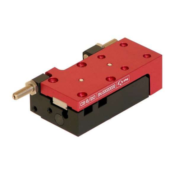
Shock absorber 5 C-Nut for sensor The CS 6 consists of the base body (1) with pneumatic connections and cylinder and the moveably mounted slide (2). The stop positions are set by means of a stop screw with integrated shock absorber (4). -
Page 14: Scope Of Supply
Modifications on the module that are not described in these Montage Instructions or have not been approved in writing by Afag are not permitted. In case of improper changes or assembly, installation, operation, maintenance or repairs, Afag rejects all liability. -
Page 15: Warranty
The CS Compact Slides are exclusively designed for the linear movement of load capacities of up to 0.1 kg (CS 6/20); (CS 6/40 to 0.1 kg), in any position on the slide and maximum 0.08 kg (CS 6/20); (CS 6/40 to 0.08 kg) at the face side of the module;... -
Page 16: Dimension Cs 6
3.1.7 Dimension CS 6 CS6-BA-vers.1.7 gb. 20190312... -
Page 17: Technical Data Cs 6
3.1.8 Technical data CS 6 CS6-BA-vers.1.7 gb. 20190312... -
Page 18: Pneumatic Connection
3.1.9 Pneumatic connection They are located at the CS 6/20 and CS 6/40 at the rear of the module body, the pneumatic connections (M3) are located on the side of the stop system. pneumatic connections are not used must be closed with the M3 studs Airtight, (1.1... -
Page 19: Preparation For Start-Up
3.2.0 Preparation for start-up If they put before the introduction only shock absorber, so that slide is absorbed in position. Air connection M3 Shock absorber Air connection M3 CAUTION The CS module must not be operated without shock absorbers installed as it may be damaged due to missing damping. NOTE Elastomer shock absorbers are actually a spring element, i.e. -
Page 20: Note For Shock Absorbers Elastomer
3.2.1 Note for shock absorbers elastomer CAUTION The elastomer shock absorber may be operated with a maximum useful load of 0.1 kg. NOTE Exceeding the indicated useful loads will lead to damage of the respective Compact slide. Elastomer-Absorber Order No: 50389768 Type Max. -
Page 21: Fitting The Proximity Switch In The Module Grooves
3.2.3 Fitting the proximity switch in the module grooves On top of the CS6 housing a C-groove for the proximity switch is available. With a proximity switch, the end positions can be queried. C- Nut for: Proximity switch Proximity switch PNP INI c10x19,5-Em-PNP-NO-M8x1 Order No: 50313987 Magnetic cylinder senor for simple teaching of 2 query positions. - Page 22 Installation of the proximity switch in the module slot On top of the case of CS modules, a C-groove for the proximity switch is available. With the proximity switch, the end positions can be queried. Assembly of the proximity switch 1.
-
Page 23: Starting Up The Module Cs
3.2.4 Starting up the module CS Set before start until the stop screws, and then the sensors Start-up of the CS compact slide Aerate the total system slowly. Pay attention to the permissible values (technical data) regarding: load capacity motion frequency moment loads on the guide system CAUTION... -
Page 24: Maintenance Instruction
4.0.0 Maintenance Instruction The shock absorbers and stop screws must undergo regular functionality checks, and be replaced if required. We recommend replacing the shock absorber after a maximum of 5 million load cycles. If shock absorbers are missing, defective or incorrectly set up, the functionality of the module will be compromised and may lead to its destruction! 4.1.0 Maintenance and servicing CAUTION... -
Page 25: Servicing
Module inserts for ionized air environments (e.g. in case of high- voltage procedures such has corona processes) Open guides and piston rods should be covered with a grease layer to avoid formation of rust. Standard greasing Afag: - Staburax NBU8EP (flat guides) - Blasolube 301 (piston rods) CS6-BA-vers.1.7 gb. 20190312... -
Page 26: Fault During Operation
4.1.2 Fault during operation Fault Possible cause Fault clearance The CS-compact swivel The stop / shock are not Adjust the stop / shock comes firmly into the set correctly. end positions Fixed strike again in the Damping elements are Replace damping elements end positions defective The CS module remains... -
Page 27: Expendable Parts For Elastomer Shock Absorbers
(Fa). This applies for the rear position with the CS 6 as the return stroke force is less than 15N. 1. Turn out the adjusting pin until... -
Page 28: Disassembly And Repair
4.1.5 Disassembly and repair When the module is damaged it can be returned to Afag Automation AG for repair. CAUTION The module may only be disassembled when the system is aerated and deactivated. If pneumatic connections are disconnected when they are under pressure, this may result in serious personal injury due to fast movements of moving parts. -
Page 29: Accessories / Spare Parts
4.1.6 Accessories / spare parts Item Order No. Sensor INI c10x19.5-Em-PNP-NO-M8x1 50313987 Elastomer shock absorber ASED M4x0.5-1 50389768 (CS 6) Absorbing element 50400874 (CS 6) Theraded pins M3x3 mm (2 Item) 50340298 Centering bushings Ø4x2 mm (2 Item) 50332257 Centering bushings Ø5x2.5 mm (2 Item) - Page 30 Afag Automation AG Fiechtenstrasse 32 CH - 4950 Huttwil Switzerland Tel.: +41 62 959 87 02 Fax.: +41 62 959 87 87 sales@afag.com www.afag.com...
Need help?
Do you have a question about the CS 6 and is the answer not in the manual?
Questions and answers