
Related Manuals for Afag DG 16


Summary of Contents for Afag DG 16
- Page 1 Rotary gripper DG 16 Declaration of Incorporation Module Information Montage Instructions Maintenance Instructions „Translation“ of the Original Montage Instructions © Copyright by Afag Automation AG...
- Page 2 These Montage Instructions apply to: Type Order No. Rotary gripper DG 16 50294010 Assembly and initial start-up must be carried out by qualified personnel only and ac- cording to these Montage Instructions. Version of this docu- DG 16-BA-v-1.9 gb. 11.11.14...
-
Page 3: Table Of Contents
Technical data of the DG 16 ................. 18 Perferred combinations of the DG 16 ............19 Loads on the gripper fingers ................. 20 3.10 Adjustment of the DG 16 rotary grippers ............20 3.11 Installation of the sensors ................20 3.12 Preparation for start-up ................. - Page 4 Further maintenance ..................24 Servicing ....................... 25 Troubleshooting .................... 26 Spare parts ....................27 Accessories ....................28 4..6 Disassembly and repair ................29 Disposal ...................... 30 Appendix ..................... 30 List of Figures ....................30 List of Tables ....................30 DG 16-BA-v-1.9 gb. 11.11.14...
-
Page 5: Ec Declaration For Incorporation
1.1.0 According to 2006/42/EC dated 09. June 2006, Appendix II B VI for Incorporation of partly completed machinery. The manufacturer: Afag Automation AG, Fiechtenstrasse 32, CH-4950 Huttwil Tel. +41 62 959 87 02, www.afag.com As manufacturer of the partly completed machine we declare that:... -
Page 6: Module Information
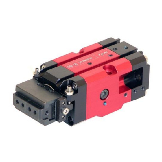
It is fitted with a parallel gripping head. The rotary gripper can be mounted vertically and horizontally. The DG 16 rotary gripper consists of the rotary drive and the rotating pliers head. The angle of rotation is 180°. An intermediate stop can be ordered as option which limits the angle of rotation to 90°. - Page 7 NOTE Please note: Modifications on the DG 16 rotary gripper that are not described in these Montage Instructions or have not been approved in writing by Afag Automation AG are not permitted. In case of improper changes or assembly, installation, operation, maintenance or repairs, Afag Automation AG rejects all liability.
-
Page 8: Installation, Connections
2.5 Installation and fastening possibilities The DG 16 rotary grippers can be installed in a vertical and horizontal position. The Afag module components are provided with a precise module centring which guarantees a high and repetitive accuracy of fit during installation, operation and ex- change of a module. -
Page 9: Tightening Moments For Screws
Pneumatic diagram DG 16. The pneumatic connections (total of 16 x M3) are fitted on four sides of the base body of the DG 16 rotary gripper. The 4 air connections (M3) at the rear of the DG 16 rotary gripper are normally open. Close air connections which are not used air-tight before installing the module in a system. - Page 10 HINWEIS Minimal compressed air quality according to ISO 8573-1; 2010 (7-4-4) 1 Rotary gripper 2 Maintenance unit 2 Directional valve 4/2 P Compressed air connection DG 16-BA-v-1.9 gb. 11.11.14...
-
Page 11: Manufacture Of Gripper Fingers
For a reliable interrogation of grasping „Part gripped“ is recommend- ed to realize in the middle of the jaw stroke and not restrict the over- all jaw. Example: DG 16 2x3mm, jaw part gripped with 2x1.5mm 2.8 Manufacture of gripper fingers The gripper fingers must be designed and manufactured for the parts to be gripped. -
Page 12: End Stop 90
2.9 End stop 90° A fixed end stop can be mounted as option on the DG 16 rotary gripper so that the rotary gripping pliers can move at an angle of 90° to the end stop from both sides. - Page 13 Mount the fixed stop using the 2 M2.5 mm Allen screws on the free side of the drive (see figure). DG 16 mounting side for the fixed stop Rotary gripper DG 16 Standard version Option: Rotary gripper DG 16 Without fixed stop Zero position at 90°...
-
Page 14: Montage Instructions
Directive 206/42/EG, where appropriate. Name and address of the person authorised to compile the relevant technical docu- mentation: Lanz Beat, PM & Marketing-Services, Afag Automation AG DG 16-BA-v-1.9 gb. 11.11.14... -
Page 15: Included In The Scope Of Delivery
Table 1: Scope of delivery 3.3 Intended use The DG 16 rotary gripper is used for the smooth rotary and gripping movement of loads in non-explosion hazardous ambient and Installation conditions that are speci- fied for this module (see Technical Data). -
Page 16: Guarantee
Modifications on the module that are not described in this Montage In- struction or have not been approved in writing by Afag are not permitted. In the case of improper changes or assembly, installation, operation, maintenance or repairs, Afag AG rejects all liability. -
Page 17: Dimensions Drawing Of The Dg 16
Use the centering sleeves included in the scope of delivery for positioning and insert these sleevs in the borings of the mounting grid. Note: It gives the DG 16 rotary gripper with the zero position at 90° on request. DG 16-BA-v-1.9 gb. 11.11.14... -
Page 18: Technical Data Of The Dg 16
3.7 Technical data of the DG 16 Table 2: Technical data of the DG 16 DG 16-BA-v-1.9 gb. 11.11.14... -
Page 19: Perferred Combinations Of The Dg 16
3.8 Perferred combinations of the DG 16 DG 16-BA-v-1.9 gb. 11.11.14... -
Page 20: Loads On The Gripper Fingers
5°. 3.11 Installation of the sensors Magnetic proximity switches can be installed in the C-grooves for end-position sens- ing of the DG 16 rotary grippers. These are specified in chapter 4 of this Montage Instructions (Accessories). CAUTION The DG 16 rotary grippers must not be used in an explosion- hazardous area. -
Page 21: Preparation For Start-Up
Proximity switch cable Order No. 50386489 3.12 Preparation for start-up After the air connections and the sensors have been installed the DG 16 rotary grip- per can be started for the first time via the system controller. DG 16-BA-v-1.9 gb. 11.11.14... -
Page 22: Start-Up
The gripper fingers are moved by the electric control. If the gripper fingers cannot move freely there is danger of injuries and bruises near the add-ons. If add-ons at the DG 16 rotary gripper could cause danger in connection with the gripper fingers a safe operation must be ensured. -
Page 23: Standard Operation
The gripper fingers are moved by the electric control. If the gripper fingers cannot move freely there is danger of injuries and bruises near the add-ons. If add-ons at the DG 16 rotary gripper could cause danger in connection with the moving gripper fingers a safe operation must be ensured. -
Page 24: Maintenance Instructions
The module must not be washed down; do not use any ag- gressive cleaners. Table 3: Maintenance works Further maintenance Under the ambient conditions mentioned below the DG 16 rotary gripper does not require any further maintenance: clean workshop atmosphere no splash water no friction dust or dust from processing climate and temperature according to the technical data. -
Page 25: Servicing
Filtered (40µm filter for oiled air) Filtered (5µm filter for unoiled air) If the DG 16 module is operated with oiled air, the oil types listed below should be used: Festo special oil Avia Avilub RSL 10 ... -
Page 26: Troubleshooting
Observe the Montage Instructions of the system into which the DG rotary gripper was incorporated. WARNING Due to the decentral controller the operator of the DG 16 rotary gripper needs not to be near the product so that third persons might be endangered by the rotary/gripper operation. -
Page 27: Spare Parts
Initiator not correctly Re-teach initiator taught Table 4: Faults, causes, fault clearanc 4.4 Spare parts Repair of the DG 16 rotary gripper should only be carried out by Afag. There are no spare parts available. DG 16-BA-v-1.9 gb. 11.11.14... -
Page 28: Accessories
4.5 Accessories Article Order No. Centering sleeves 5x2.5mm 50035831 Centering sleeves 8x3.5mm 50263565 Magnetic cylinder sensor for simple teaching of 2 query poitions. Proximity switch cable Article No. 50386489 DG 16-BA-v-1.9 gb. 11.11.14... -
Page 29: Disassembly And Repair
Table 5: Accessories 4.6 Disassembly and repair When the module is damaged it can be returned to Afag Automation AG for repair. CAUTION Switch off and secure the controller before the DG 16 rotary gripper is removed out of the system. -
Page 30: Disposal
5.0 Disposal NOTE DG 16 rotary modules which cannot be used any more must not be disposed of as a complete unit, but must be disassembled and recy- cled according to the type of material. Materials than cannot be recycled must be disposed of in accord- ance with the legal regulations. - Page 31 DG 16-BA-v-1.9 gb. 11.11.14...
- Page 32 Afag Automation AG Fiechtenstrasse 32 4950 Huttwil Switzerland Phone: +41 62 959 86 86 Fax: +41 62 959 87 87 e-mail: sales@afag.com Internet: www.afag.com DG 16-BA-v-1.9 gb. 11.11.14...
Need help?
Do you have a question about the DG 16 and is the answer not in the manual?
Questions and answers