
Related Manuals for Compool CP3000


Summary of Contents for Compool CP3000
- Page 1 Compool Cp3000 POOL-SPA CONTROL SYSTEM Installation & Operating Instructions 01/01/95 941-0881...
-
Page 3: Table Of Contents
SYSTEM START-UP ................19 CALIBRATING TEMPERATURE SENSORS .......... 20 OPERATING INSTRUCTIONS............21 INTRODUCTION..................21 SAFETY FEATURES ................21 Cp3000 CONTROLLER ................22 PROGRAMMING ..................27 Lx3000 POWER CENTER ............... 30 VALVE ACTUATORS ................32 SPA-SIDE REMOTE ................32 SYSTEM OPTIONS ................. 34 MAINTENANCE................ -
Page 4: Safety Notice
Compool Cp3000 Safety Notice SAFETY NOTICE IMPORTANT SAFETY INSTRUCTIONS WHEN INSTALLING AND USING THIS ELECTRICAL EQUIPMENT, BASIC SAFETY PRECAUTIONS SHOULD ALWAYS BE FOLLOWED, INCLUDING THE FOLLOWING: • READ AND FOLLOW ALL INSTRUCTIONS. • WARNING: TO REDUCE THE RISK OF INJURY, DO NOT PERMIT CHILDREN TO USE THIS PRODUCT UNLESS THEY ARE CLOSELY SUPERVISED AT ALL TIMES. -
Page 5: Installation
Modular Plugs for Communication Cable (3 qty) Test Cable with Modular Plugs (4 ft.) SPECIAL TOOLS REQUIRED 3/16” dia. Drill (for mounting Cp3000 Controller). 5/16” dia. Drill (for mounting Water Temperature Sensor). Crimping Tool (model TOOL-6) for mounting Connectors to Hookup Cable. -
Page 6: Plumbing Requirements
Installation Compool Cp3000 PLUMBING REQUIREMENTS VACUUM RELIEF CP-3000 LX-3000 SOLAR CONTROLLER SERVICE CENTER SENSOR SOLAR PUMP HW-5B FILTER FILTER PUMP HEATER CVA-24 PUMP POOL CVA-24 CLEANER INTAE PUMP SIMMER CVA-24 BLOWER POOL LIGHT MAIN DRAIN POOL WATERFALL LIGHT Recommended Hydraulic Schematic Plumb system in accordance with recommended hydraulic schematic, local codes and the following guidelines. -
Page 7: Equipment Location
3-port Compool Solar Valve at the solar feed line. Provide a vacuum relief valve at the highest point of the solar panel array, and a ½ lb. spring check valve at the solar return line. Use Compool Solar Valve (model SOL-2T), to allow the panels to automatically drain whenever the filter pump is not running. -
Page 8: High Voltage Wiring
Installation Compool Cp3000 HIGH VOLTAGE WIRING SUB-PANEL At the equipment site, install an electrical sub-panel with separate breakers for each load. Circuit breakers should be readily accessible to the pool/spa user, but installed at least 5 feet from the water’s edge. - Page 9 Provide a separate circuit breaker to power the system. Either 115 or 230 VAC can be used (115 VAC is preferable). The Cp3000 system draws less than 1 amp. Caution: Incorrect system wiring will cause permanent damage to the transformer.
- Page 10 ADDING RELAYS The Cp3000 system comes standard with 4 power relays for activating the Filter Pump, Aux1, Aux2 and Aux3 circuits. It is possible to install additional Relay Kits (model RLY-LX) to the Lx3000, in order to activate additional equipment.
- Page 11 Installation Compool Cp3000 UNDERWATER LIGHTS LINE LINE LOAD LOAD LINE LINE LOAD LOAD LINE LINE LOAD LOAD LINE LINE LOAD LOAD LINE LINE LOAD LOAD LINE LINE LOAD LOAD LINE LINE LOAD LOAD If the system incorporates 115 Volt Underwater Light(s), you should provide GFCI protection on the load side of the relay (not the line side) as shown above.
-
Page 12: Low Voltage Wiring
Installation Compool Cp3000 LOW VOLTAGE WIRING VLV1 VLV2 WITH WITH VLV2 VLV3 VLV1 VLV2 VLV3 COMPOOL 11040A MOD-VLV3 TRANSFORMER CONNECTIONS INTAKE RETURN SOLAR VALVE VALVE VALVE FLTR ACTUATOR ACTUATOR ACTUATOR AUX1 AUX2 AUX3 AUX4 AUX5 AUX6 FLTR SOLR AUX1 SOLAR... - Page 13 (model TOOL-6) to connect modular plug at each end of cable. See USING THE CRIMPING TOOL for details. At the Cp3000, insert cable (with modular plug attached) into circuit board at “LINE TO LX” Socket.
- Page 14 Installation Compool Cp3000 Use the four ½” screws (included) to mount Controller to the backplate. At the Lx3000, insert cable (with modular plug attached) into circuit board at “to CP-3000” Socket. USING THE CRIMPING TOOL TOOL-6 Use Cutter to prepare cable end. Make sure that cable is cut squarely (not diagonally).
- Page 15 Installation Compool Cp3000 • Plug Intake (suction) Valve to INT VLV Socket. • Plug Return Valve to RET VLV Socket. • Plug Optional Solar Valve (if applicable) to SOL VLV Socket. Note: To control additional valve actuators, see AUXILIARY VALVE ACTUATORS for details.
- Page 16 Installation Compool Cp3000 leads to about 6”. Do not strip wires. Push the 2 wires to be connected into the small holes at one end of the connector, and squeeze the connector with a pair of pliers. 2 extra connectors are included.
-
Page 17: System Options
Installation Compool Cp3000 SYSTEM OPTIONS SPA-SIDE REMOTE SS4-100W The optional Spa-Side Remote (model SS4-100W) is a double-insulated device which is UL Listed for installation within 5 feet of the water’s edge. It is typically installed at the tile-line on the spa wall (above water level), or in the deck within arm’s reach of the spa. - Page 18 Installation Compool Cp3000 A set of adhesive labels is provided for custom identification of individual Spa-Side Remote buttons. Use a pair of fine-tip tweezers to carefully adhere the appropriate label at each button. 2-SPEED FILTER PUMP CONTROL If the system is equipped with a 2-Speed Filter Pump, a 2-Speed Filter Pump Relay Kit (model RLY-LXD) should be installed at the Power Center in accordance with instructions provided.
- Page 19 Activates AUX6 during freezing conditions. When Freeze Mode starts, the Cp3000 display will indicate “FRZ” and turn on any circuit that has been selected by the FREEZ PROT Program Switch. Equipment key icons will not show “ON” if activated by the Freeze Mode.
- Page 20 Installation Compool Cp3000 any of the equipment keys on the Cp3000 controller will deactivate the Freeze Mode. SOLAR TEMPERATURE SENSOR If the system incorporates solar, install an optional Temperature Sensor (model TS-5L) at the solar panel array. Adjust the 2-position Program Switch, which is located at top center of Lx3000 circuit board. Use the corner of a small screwdriver or other blunt instrument to slide Switch #1 (SOLAR) to the ON position.
- Page 21 To enable this feature, it is necessary to adjust the 3-position S1 Program Switch, which is located at top right-side of Cp3000 circuit board. Using the corner of a small screwdriver or other blunt instrument, slide Switch #3 to the ON position.
-
Page 22: System Start-Up
“Auto” mode. 10. At the Cp3000 Controller, press each Equipment Key (#S, #P, #1, #2, #3 and #4), and check that appropriate equipment is being activated. Note: If the Auto/Service Key at the Lx3000 has inadvertently been left in the “Service”... -
Page 23: Calibrating Temperature Sensors
Use a thermometer to verify pool temperature. Use a thermometer to verify solar temperature if applicable. At the Cp3000 Controller, turn on the Pool and let it run for a few minutes. Press the Program Key. Press the Pool Heat Source Key. ADJ 1 will appear on the Display. -
Page 24: Operating Instructions
Compool Cp3000 OPERATING INSTRUCTIONS INTRODUCTION The Cp3000 is an electronic control system which is designed to coordinate and operate all of the equipment associated with your swimming pool and spa. The system is comprised of three principal components: • Cp3000 Controller. -
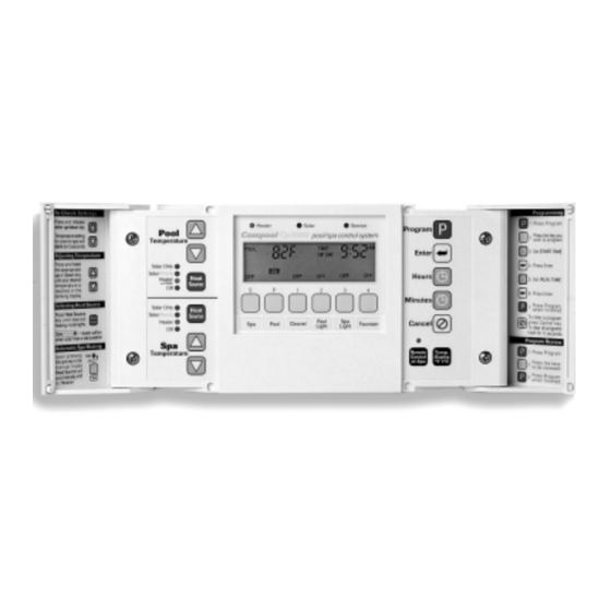
Page 25: Cp3000 Controller
Cp3000 CONTROLLER Installed in a convenient location inside your house, the Cp3000 Controller gives you fingertip control of all the equipment associated with your swimming pool and spa. EQUIPMENT STATUS LAMPS... - Page 26 Operating Instructions Compool Cp3000 Heater: Indicates whenever the heater is on. Solar: Indicates whenever the solar system (if applicable) is running. Service: Indicates whenever the equipment is being operated from the equipment site (i.e. the Auto/Service Key at the Lx3000 Power Center is in the Service position).
- Page 27 Operating Instructions Compool Cp3000 Key #2: Activates auxiliary equipment (such as a pool light). Key #3: Activates auxiliary equipment (such as a spa light). Key #4: Activates auxiliary equipment (such as a fountain). USING YOUR SPA To turn your Spa ON, simply press Key #S. The motorized valves will rotate to “spa circulation” position, the filter pump will turn on, and the heater will heat the spa to the pre-selected spa temperature.
- Page 28 Note2: For added convenience, whenever the spa is manually activated (from either the Cp3000 Controller or the Spa- Side Remote), the Spa Heat Source Lamp will automatically switch to “Heater” and heating will begin. Turning the spa off will return Spa Heat Source Lamp to its previous position.
- Page 29 Operating Instructions Compool Cp3000 SETTING THE CLOCK To set the Display to the correct TIME OF DAY, press the Hours and Minutes Keys (located behind the right-side door of the Cp3000 Controller). Pay attention to the AM/PM symbols on the Display.
-
Page 30: Programming
Most systems only require that you program the pool filtration cycles (Key #P) and, in some cases, pool cleaning cycles (Key #1). However, it is possible to program equipment connected to any of the six Equipment Keys at the Cp3000 Controller. - Page 31 Operating Instructions Compool Cp3000 MULTIPLE PROGRAMS A total of four operating cycles may be programmed each piece of equipment. To program multiple operating cycles, follow steps 1 to 6 on the BASIC PROGRAM, and then press the Equipment Key a second time. The display will indicate PROG 2, plus a blinking START TIME.
- Page 32 ONCE ONLY PROGRAM It is possible to program a “ONCE ONLY” program for any of the Equipment Keys on the Cp3000. When a ONCE ONLY program is executed, it is erased automatically. This feature is useful to program the Spa in advance so it will be ready for use within a 24 hour period.
-
Page 33: Lx3000 Power Center
Located in close proximity to your pool and spa equipment, the Lx3000 Power Center provides your Pool Serviceperson with manual control of the system without having to gain access to the Cp3000 Controller. Caution: To prevent possible water damage, the door of the Lx3000 must be kept closed at all times. - Page 34 Manually activates the filter pump. Key #1: Manually activates equipment connected to Aux1 circuit. Overrides Equipment Key #1 at the Cp3000 Controller. Note: If the system incorporates an automatic pool cleaner, it is controlled by this circuit. Keys #2 - #4: Manually activates equipment connected to Aux2 through Aux4 circuits.
-
Page 35: Valve Actuators
SPA-SIDE REMOTE One or more 4-button waterproof Remote Controls may be located at your spa. This will enable you to override the Cp3000 Controller, and manually activate your spa equipment from the convenience of the spa. - Page 36 To achieve this, press the “Remote Control at Spa” Key, which is located behind the right-side door of the Cp3000 Controller. If the status lamp is illuminated, the Remote Control is operational. If the status lamp is not illuminated,...
-
Page 37: System Options
2-SPEED FILTER PUMP CONTROL If your system incorporates a 2-Speed Filter Pump, the Cp3000 has been designed to provide you with the maximum energy- efficient usage of this feature. See 2-SPEED FILTER PUMP CONTROL in the Installation section for details. -
Page 38: Maintenance
At the electrical supply panel, turn off the pool cleaner circuit breaker (if applicable). At the Cp3000 Controller, press the Pool Heat Source Key until “Off” Status Lamp is illuminated. If your control system incorporates solar, ensure that the panels are completely drained. To inactivate the Solar Temperature Sensor, it is necessary to adjust the “FEATURES”... - Page 39 REPLACING THE BACK-UP BATTERY There is a small 3-Volt lithium battery located inside the Cp3000 Controller. In the absence of power, this battery will keep the clock running and retain the programming in memory for approximately 2 years. The display will be blank during power failure.
-
Page 40: Problem Solving
At the Cp3000 Controller, make sure that either the pool or spa is being circulated. The Cp3000 system has a 10 ° Fahrenheit solar differential. This means that if the pool temperature is 80 ° Fahrenheit, the solar temperature must be 90 ° Fahrenheit or higher before the solar system is activated. - Page 41 At the Lx3000 circuit board, locate 7-position “FREEZ PROT” Program Switch, and determine which circuits have been selected for freeze protection. SPA-SIDE REMOTE NOT WORKING At the Cp3000 Controller, locate the “Remote Control at Spa” Key (behind right-side door), and verify that status lamp is on. SPA-SIDE EQUIPMENT TURNS OFF AFTER 30 MINUTES This is a normal function for Aux5 and Aux6 circuits.
-
Page 42: Warranty
Compool Corporation; or which have been damaged because of a defect in a component or part which is not part of the Compool Control System; or upon which the serial number or manufacture date has been altered, effaced or removed. -
Page 43: Index
Compool Cp3000 Index INDEX MAINTENANCE 35 MOD-VLV3 15 NUMERICS MOUNTING THE CP3000 CONTROLLER 10 2-SPEED FILTER PUMP CONTROL 15 MULTIPLE PROGRAMS 28 3-HOUR FILTER OVERRIDE 31 ONCE ONLY PROGRAM 29 ADDING CHEMICALS 35 OPERATING INSTRUCTIONS 21 ADDING RELAYS 7 OVERRIDING THE SAFETY DELAY CIRCUITS 22...
Need help?
Do you have a question about the CP3000 and is the answer not in the manual?
Questions and answers