
Related Manuals for Compool Cp3800


Summary of Contents for Compool Cp3800
- Page 1 Compool Cp3800 POOL-SPA CONTROL SYSTEM Installation & Operating Instructions 11/07/97 941-1064...
-
Page 3: Table Of Contents
Compool Cp3800 Table of Contents Safety Notice............3 Important Safety Instructions . - Page 4 Compool Cp3800 System Start-up........... 24 Operating Instructions.
-
Page 5: Safety Notice
Compool Cp3800 Safety Notice Important Safety Instructions When installing and using this electrical equipment, basic safety precautions should always be followed, including the following: Read and follow all instructions. To reduce the risk of injury, do not permit children to use this product unless they are closely supervised at all times. -
Page 6: Introduction
Compool Cp3800 Introduction Package Contents The CP3800/T system includes the following components. CP-3800 Control Panel (w/ cable) (1 qty.). LX-3800 Power Center (1 qty.). CVA-24T Valve Actuator (2 qty.). PTV-2T 3-Port Valve (2 qty.). SNS-KIT2 Sensor Kit (1 qty.). - Page 7 Compool Cp3800 The CP3800/TL system includes the following components. CP-3800 Control Panel (w/ cable) (1 qty.). LX-3800L Power Center (1 qty.). CVA-24T Valve Actuator (2 qty.). PTV-2T 3-Port Valve (2 qty.). SNS-KIT2 Sensor Kit (1 qty.).
-
Page 8: Plumbing Requirements
Compool Cp3800 Plumbing Requirements VACUUM RELIEF FREEZE SOLAR CONTROL PANEL POWER CENTER SENSOR SENSOR SOLAR PUMP FILTER FILTER PUMP HEATER CVA-24 PUMP CVA-24 INTAKE CLEANER PUMP SKIMMER CVA-24 BLOWER POOL LIGHT MAIN DRAIN POOL WATERFALL LIGHT Plumb system in accordance with recommended hydraulic schematic. -
Page 9: Equipment Location
Plumb solar feed and return lines between the filter and heater. Install 3-port solar valve at the feed line. Use Compool solar valve (model SOL-2T), to allow automatic draining of panels. 10. A solar booster pump should be used when distance to panels exceeds 200’, or panels are elevated higher than 25’. -
Page 10: Installation
Compool Cp3800 Installation High Voltage Wiring Power Center with built in Sub-panel At the equipment pad, mount the Power Center within 15’ of all the equipment. Provide power from the Main-panel (located at the house) to Power Center. Power Center without built in Sub-panel... -
Page 11: System Power
Compool Cp3800 System Power SUB-PANEL Lx3800 System Power provides power to the transformer. • To wire System Power At the Sub-panel, install a circuit breaker for System Power. The system draws less than 1 amp. Do not use a GFCI circuit breaker. -
Page 12: Equipment Power
Compool Cp3800 Equipment Power SUB-PANEL LINE 1 LINE 2 LOAD 1 LOAD 2 LINE 1 LINE 2 LOAD 1 LOAD 2 LINE 1 LINE 2 LOAD 1 LOAD 2 LINE 1 LINE 2 LOAD 1 LOAD 2 LINE 1 LINE 2... -
Page 13: Underwater Lights
Compool Cp3800 Underwater Lights SUB-PANEL LINE 1 LINE 2 LOAD 1 LOAD 2 LINE 1 LINE 2 LOAD 1 LOAD 2 LINE 1 LINE 2 LOAD 1 LOAD 2 LINE 1 LINE 2 LOAD 1 LOAD 2 LINE 1 LINE 2... -
Page 14: Low Voltage Wiring
Compool Cp3800 Low Voltage Wiring Power Center Circuit Board VLV2 VLV1 CONTROL WITH WITH JUMPERS VLV3 VLV2 COMBINED VALVES VLV1 VLV2 COMPOOL 11040A VLV3 PART# MOD-VLV3 TRANSRER CNNECTINS INTAKE RETURN VALVE VALVE VALVE ACTUATOR ACTUATOR ACTUATOR CNTRL FLTR AUX1 AUX2... -
Page 15: Low Voltage Cables
Compool Cp3800 Low Voltage Cables Control Panel 6-conductor cable runs between the Control Panel and the Power Center. Heater Connection 2-conductor cable runs between the heater and the Power Center. Water Temperature Sensor 2-conductor cable runs between the Water Temperature Sensor and the Power Center. -
Page 16: Gas Heater Connections
Compool Cp3800 AUX VLV CNTRL socket and relay socket of choice. The system ships with the jumper connected between AUX VLV CNTRL and SOL PUMP. Note To control more than three Valve Actuators, see Valve Module for details. Gas Heater Connections... -
Page 17: Freeze Temperature Sensor
Compool Cp3800 At the sensor, use crimp connectors (included) to provide waterproof connections. Before making connections, cut off stripped ends of cable. Insert the 2 wires to be connected into the connector and squeeze the connector with a pair of pliers. Two extra connectors are included. -
Page 18: Control Panel
Compool Cp3800 Control Panel • To install the Control Panel Select a location inside the house or other weather-protected area to mount the Control Panel. The Control Panel should be installed at or below eye level. Remove backplate from Control Panel. Position backplate and mark the three mounting points. -
Page 19: Modular Crimping Tool
Compool Cp3800 Modular Crimping Tool The Crimping Tool is required to attach modular connectors to the Hookup Cable. The tool may be purchased from a pool supply store (model TOOL-6). If purchasing from an electrical supply store, verify it is designed to crimp 6-position connectors. -
Page 20: System Options
Compool Cp3800 System Options Spa-side Remote The Spa-side Remote is typically installed in the tile-line of the spa. See Plumbing Requirements for details. • To install the Spa-side Remote When spa construction is completed, cut back the 1.5” dia. pvc pipe flush to the tile. -
Page 21: Multiple Control Panels
Compool Cp3800 Activates Spa mode. REM1 Activates AUX1 equipment. REM2 Activates AUX2 equipment. REM3 Activates AUX3 equipment REM4 Activates AUX4 equipment. REM5 Activates AUX5 equipment. REM6 Activates AUX6 equipment. REM7 Activates AUX7 equipment. Use labels provided to identify each button on the Spa-side Remote. -
Page 22: Heat Pump Or Electric Heater
Compool Cp3800 Heat Pump or Electric Heater These heaters require a relay kit (model RLY-LX) be added. The HTR connection used for gas heaters cannot used. • To wire a heat pump or electric heater. At the Power Center, install the relay into the high voltage compartment. Plug control wire into the EHTR relay socket on the Power Center circuit board. -
Page 23: Two Speed Filter Pump
Compool Cp3800 control wire of relay into SOL PMP relay socket. Two Speed Filter Pump If the system is equipped with a 2-speed filter pump, install a 2-speed relay kit (model RLY- LXD) into Power Center. There are two ways to configure the 2-Speed filter pump. -
Page 24: Backwash Control
Compool Cp3800 Power Center circuit board. Backwash Control The backwash control system is designed to automatically backwash the filter on a timed basis. This feature uses the AUX7 circuit to control the two backwash valves. To install an automatic backwash system, you must have a sand filter with a side inlet and outlet. -
Page 25: Configuration Switches
Compool Cp3800 Configuration Switches POOL HEAT 1 2 3 4 5 1 2 3 4 5 1 2 3 4 5 1 2 3 4 FREEZE SYST SPEC FUNCT HI SPD After setting configuration switches, turn system power off for a few seconds. -
Page 26: Hi Spd - High Speed
Compool Cp3800 A7BW Activate backwash for AUX7 circuit. A730 Activate 30 minute time-out for AUX7 circuit. HI SPD - High Speed High Speed settings are used to configure the following equipment. Activate high speed when spa is on. Activate high speed when heater is on. -
Page 27: Operating Instructions
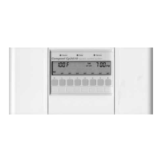
Compool Cp3800 Operating Instructions Control Panel Installed at a convenient location inside the house, the Control Panel provides complete control of all the equipment associated with your swimming pool and spa. The system comes with one Control Panel, however additional Control Panels may be added as needed. -
Page 28: Equipment Status Lamps
Compool Cp3800 A solid OFF indicates the equipment is off. A blinking ON indicates the cleaner is in a safety delay mode. The cleaner will turn on in 5 minutes. A blinking OFF indicates the heater is in a cool down mode. The pool will turn off after 10 minutes. -
Page 29: Temperature Control
Compool Cp3800 Temperature Control Located behind the left door of the Control Panel is the Temperature Control area. Heating choices are selected using the following keys. Heat Source key To select heating method, press the Heat Source key through the different heating options. -
Page 30: Fahrenheit/Celsius Key
Compool Cp3800 Fahrenheit/Celsius key Located behind the right-door of the Control Panel is the Temp. Display key. Press this key to select Fahrenheit or Celsius temperature display. Programming Behind the right door of the Control Panel are the keys used to Program equipment. -
Page 31: Programming
Compool Cp3800 Programming Typically only the Pool key (Pool filtration) needs to be programmed. Other Equipment keys can be programmed the same way. • To program Pool filtration Press the Program key. Press the Pool key. Press the Hours/Minutes key to set the START TIME. -
Page 32: Programming A Once-Only
Compool Cp3800 Follow Programming example, set START TIME to 0:00 hours. Set RUN TIME to the number of Hour/Minutes before equipment should Time-out. Note If the RUN TIME is set for 24 hours, manually activated equipment will run continuously until manually turned off. -
Page 33: Calibration
Compool Cp3800 Calibration The temperature sensors, backwash, and floor cleaner valve can be adjusted in the calibration mode. Allow pool to run 5 minutes before calibrating the Water Temperature Sensor. • To calibrate equipment Press the Program key. Press the Spa Heat Source key. - Page 34 Compool Cp3800 Note Solar, backwash, and floor cleaner valve adjustments are skipped if feature is not enabled. Tips for calibrating the temperature sensors Water Sensor Let the pool run for 5 minutes to allow water temperature sensor to accurately pickup current pool water temperature.
-
Page 35: Power Center
Compool Cp3800 Power Center Equipment keys Located at the equipment pad, the Power Center provides manual-override capability of your equipment. Caution To prevent water damage, close Power Center door after use. The Auto/Service key toggles the Power Center between the following modes. -
Page 36: Hour Filter Override
Compool Cp3800 The S key toggles the Intake and Return Valve Actuators through the following options. Spa circulation. Fill spa. Drain spa. No status lamp indicates valves are in pool circulation. The P key turns on the Filter Pump. Keys 1-7 activate auxiliary equipment. -
Page 37: Spa-Side Remote
Compool Cp3800 Spa-side Remote The Spa-side Remote allows controlling your equipment from the spa. The light in the middle of the switch will turn on whenever the spa is on. The light will blink when the spa is being heated. -
Page 38: System Options
Compool Cp3800 System Options Telephone Module The Telephone Module can control your equipment from inside your home or by calling your home from a remote location. The Telephone Module is most often setup to control the spa, however if the home is a vacation home, you may want to configure it to turn on your pool heater instead. -
Page 39: Winterizing The System
Compool Cp3800 Winterizing the System In areas where freezing temperatures occur for an extended period of time, it is required to consult a qualified service company to winterize your pool. -
Page 40: Troubleshooting
Compool Cp3800 Problem Solving Display shows “Err 1” If there is a fault with the Water Temperature Sensor, the display will show “Err 1”. Check sensor cable and connections. Replace Water Temperature Sensor (model TS-5L). Display shows “Err 2” If there is a fault with the Solar Temperature Sensor, the display will show “Err 2”. - Page 41 Compool Cp3800 Heat Source does not allow Solar At the Power Center circuit board, the SPEC FNCT configuration switch SOLR needs to be turned on. See Configuration Switches for details. Solar heating stops too soon Verify solar temperature is calibrated correctly. See Calibration for details.
-
Page 42: Warranty
Compool, Inc.; or which have been damaged because of a defect in a component or part which is not part of the Compool Control System; or upon which the serial number or manufacture date has been altered, effaced or removed. -
Page 43: Index
Compool Cp3800 Index 2-speed Filter Pump Control 36 3 - Hour Filter Override 34 Adding Relays 10 Backwash Control 22 Calibration 31 Canceling Heater and Cleaner Protection 26 Canceling Programs 30 Cleaner Protection 26 Configuration Switches 23 Control Panel 16... - Page 44 Compool Cp3800 Power Center without built in Sub-panel 8 Problem Solving 38 Programming 28 Programming 29 Programming a Once-only 30 Programming a Time-out 29 Programming additional Run Times 29 Remote Control at Spa key 30 Safety Notice 3 Sensor Status 34...
Need help?
Do you have a question about the Cp3800 and is the answer not in the manual?
Questions and answers
Hello , My Lx3800 uses a 110 feed for the power center I see it terminates on #2 & #3 manual shows a black / black- blue and Black- yellow My Transformer has a Black a Yellow and a purple wire for the 110 system hookup. Are two of the wires on terminal 2? and the black on terminal 3. Thanks for your help.
For a 110V feed system using the Compool Cp3800 Power Center:
1. At the sub-panel, install a circuit breaker.
2. Run the hot (line) wire from the circuit breaker to LINE 1 on the relay terminal block.
3. Connect a neutral wire to LINE 2 on the relay terminal block.
4. Connect the equipment to LOAD 1 and LOAD 2 on the same relay.
5. If the pump is greater than 3 H.P., use an external contactor and let the relay switch the contactor coil.
Ensure proper grounding and follow electrical codes.
This answer is automatically generated