Table of Contents
Advertisement
AIR-COOLED LIQUID CHILLERS
HERMETIC SCROLL
Supersedes 150.72-NM1 (110)
Form 150.72-NM1 (1020)
INSTALLATION, OPERATION, MAINTENANCE
035-21911-000
YLAA0070 - YLAA0175
AIR-COOLED SCROLL CHILLERS
WITH MICROCHANNEL CONDENSER COILS
STYLE A (60 Hz)
70 - 175 TON
246-613 KW
Interim
R-410A
Products are produced at a
f a c i l i t y w h o s e q u a l i t y -
management systems are
ISO9001 certified.
Advertisement
Table of Contents
Troubleshooting

Related Manuals for Johnson Controls YORK Tempo YLAA Series


Summary of Contents for Johnson Controls YORK Tempo YLAA Series
- Page 1 AIR-COOLED LIQUID CHILLERS HERMETIC SCROLL Supersedes 150.72-NM1 (110) Form 150.72-NM1 (1020) INSTALLATION, OPERATION, MAINTENANCE 035-21911-000 YLAA0070 - YLAA0175 AIR-COOLED SCROLL CHILLERS WITH MICROCHANNEL CONDENSER COILS STYLE A (60 Hz) 70 - 175 TON 246-613 KW Interim R-410A Products are produced at a f a c i l i t y w h o s e q u a l i t y - management systems are ISO9001 certified.
- Page 2 NOT be installed inside the panel. NO external wiring is al- lowed to be run through the micro panel. All wiring must be in accordance with Johnson Controls published specifications and must be performed ONLY by qualified Johnson Controls personnel. Johnson Controls will not be responsible for damages/problems resulting from improper connections to the controls or application of improper control signals.
- Page 3 Johnson Controls literature is available. Engineered Systems Service office or accessing the Johnson Controls Knowledge Exchange website at https://docs.johnsoncontrols.com/chillers/...
- Page 4 FORM 150.72-NM1 (1020) THIS PAGE INTENTIONALLY LEFT BLANK JOHNSON CONTROLS...
-
Page 5: Table Of Contents
Power Options .............................22 Control Options ...........................22 Compressor, Piping, Evaporator Options ..................22 Condenser and Cabinet Options ......................23 UNIT COMPONENTS ..........................25 CONTROL / POWER PANEL COMPONENTS ..................27 PRODUCT IDENTIFICATION NUMBER (PIN) ..................29 BASIC UNIT NOMENCLATURE ......................29 PROCESS AND INSTRUMENTATION DIAGRAM .................35 JOHNSON CONTROLS... - Page 6 Load Limit Input ...........................43 Flow Switch Input ..........................43 COMPRESSOR HEATERS ........................43 RELIEF VALVES ............................43 HIGH PRESSURE CUTOUT ........................43 SINGLE-POINT SUPPLY CONNECTION – TERMINAL BLOCK, NON-FUSED DISCONNECT SWITCH OR CIRCUIT BREAKER ......................44 USER CONTROL WIRING INPUTS ......................45 USER CONTROL WIRING OUTPUTS .....................46 JOHNSON CONTROLS...
- Page 7 SLRS Seismic Isolator Installation and Adjustment ..............113 One Inch Deflection Spring Isolator Cross-reference ..............114 Installation of 1” Deflection Mounts ....................115 Neoprene Isolator Cross-reference ....................116 Two Inch Deflection, Seismic Spring Isolator Cross-reference - SLRS ........117 SLRS Seismic Isolator Installation and Adjustment ..............118 JOHNSON CONTROLS...
- Page 8 Battery Back-up ..........................126 Transformer ............................126 Programming # of Compressors ......................126 STATUS KEY ............................127 Unit Status ............................127 General Status Messages .........................127 Fault Safety Status Messages ......................129 System Safeties ..........................129 Unit Safeties ............................131 Unit Warning ............................131 Status Key Messages ........................132 JOHNSON CONTROLS...
- Page 9 EVAPORATOR PUMP CONTROL AND YORK HYDRO KIT PUMP CONTROL .......159 EVAPORATOR HEATER CONTROL .....................159 PUMPDOWN CONTROL .........................159 STANDARD CONDENSER FAN CONTROL ..................159 LOAD LIMITING ............................163 COMPRESSOR RUN STATUS .......................163 ALARM STATUS ............................163 BAS/EMS TEMPERATURE RESET USINGA VOLTAGE OR CURRENT SIGNAL ......164 JOHNSON CONTROLS...
- Page 10 ON-BOARD BATTERY BACK-UP ......................177 EVAPORATOR HEATER .........................177 OVERALL UNIT INSPECTION .......................177 BACNET, MODBUS AND YORKTALK 2 COMMUNICATIONS ............178 BACnet and Modbus Communications ...................181 Communications Data Map Notes ....................181 Yorktalk 2 Communications ......................185 TEMPERATURE CONVERSION CHART ....................189 R410A PRESSURE TEMPERATURE CHART ..................190 JOHNSON CONTROLS...
- Page 11 FIG. 28 – CONDENSER FAN LOCATIONSWIRING DIAGRAMS ............160 FIG. 29 – MICROBOARD LAYOUT ......................168 FIG. 30 – I/O BOARD RELAY CONTACT ARCHITECTURE ...............172 FIG. 31 – PRINTER TO MICROBOARD ELECTRICAL CONNECTIONS ..........173 FIG. 32 - MICRO PANEL CONNECTIONS ....................179 JOHNSON CONTROLS...
- Page 12 FORM 150.72-NM1 (1020) THIS PAGE INTENTIONALLY LEFT BLANK JOHNSON CONTROLS...
- Page 13 TABLE 28 – MINIMUM, MAXIMUM AND DEFAULT VALUES .............179 TABLE 29 – VALUES REQUIRED FOR BAS COMMUNICATION ............180 TABLE 30 – REAL TIME ERROR NUMBERS ..................180 TABLE 31 - BACNET AND MODBUS COMMUNICATIONS DATA MAP ...........182 TABLE 32 - YORKTALK 2 COMMUNICATIONS DATA MAP ..............186 JOHNSON CONTROLS...
- Page 14 FORM 150.72-NM1 (1020) THIS PAGE INTENTIONALLY LEFT BLANK JOHNSON CONTROLS...
-
Page 15: Section 1 - General Chiller Information And Safety
• ANSI/ASHRAE Standard 15- Safety Code for Mechanical Refrigeration. WARRANTY • ANSI/NFPA Standard 70- National Electrical Johnson Controls warrants all equipment and materials Code (N.E.C.). against defects in workmanship and materials for a period of eighteen months from date of shipment, or 12 •... -
Page 16: Responsibility For Safety
This manual and any other document supplied with the requirements listed above. However, the individual unit are the property of Johnson Controls which reserves operating or working on any machinery is primarily all rights. They may not be reproduced, in whole or... -
Page 17: Pressure Systems
The use of gloves is recommended. Frame rails, brakes, and other components may also have sharp edges. Reasonable care should be taken when working in contact with any components to avoid risk of minor abrasions and lacerations. JOHNSON CONTROLS... - Page 18 FORM 150.72-NM1 (1020) THIS PAGE INTENTIONALLY LEFT BLANK JOHNSON CONTROLS...
-
Page 19: Section 2 - Product Description
-20º F (-29º C) ambient. code for mechanical refrigeration, ASME, and rated in The cooler is covered with ¾” flexible, closed cell, foam accordance with ARI Standard 550/590. insulation (K = 0.25). JOHNSON CONTROLS... -
Page 20: Condenser
All controls are contained in a NEMA 3R/12 cabinet • Set time with hinged outer door and includes Liquid Crystal • Set unit options Display with Light Emitting Diode backlighting for outdoor viewing: • Two display lines • Twenty characters per line JOHNSON CONTROLS... -
Page 21: Communications
• Optional communication available for N2 and • Discharge pressure (optional) LON via eLink option • Liquid Temperature Reset via a Johnson Controls ISN DDC or Building Automation System (by HIGH AMBIENT KIT others) via a 4 to 20 milliamp or 0 to10 VDC input. -
Page 22: Accessories And Options
(Factory-mounted) 5% capacity (depending on both the unit and operating conditions) by introducing an artificial load on the cooler. Hot gas by-pass is installed on only refrigerant system #1 on two-circuited units. (Factory-mounted) JOHNSON CONTROLS... -
Page 23: Condenser And Cabinet Options
150 Psig (10.5 Bar) DWP chlorine and fluorine in concentrations greater than 100 ppm). For standard units. Johnson Controls model F61MG-1C Vapor-proof SPDT, NEMA 3R switch (150 PSIG [10.5 Enclosure Panels (Unit) bar] DWP), - 20°F to 250°F (- 29°C to 121°C), with Tamperproof Enclosure Panels prevent unauthorized 1”... - Page 24 - Lower RPM, 8-pole fan mo- • Ultra Quiet Fans tors are used with steeper-pitch fans. (Factory- mounted) Vibration Isolators Level adjusting, spring type 1” (25.4mm) or seismic deflection or neoprene pad isolators for mounting under unit base rails. (Field-mounted) JOHNSON CONTROLS...
-
Page 25: Unit Components
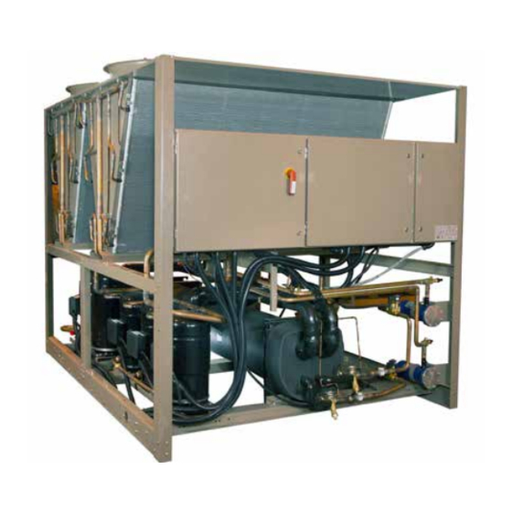
FORM 150.72-NM1 (1020) UNIT COMPONENTS ASSEMBLIES CONDENSER CONDENSER COIL COILS CONTROL PANEL POWER POWER PANEL PANEL SIGHT GLASS FILTER DRIERS LD13245 COMPRESSORS EVAPORATOR FIG. 1 – UNIT COMPONENTS FRONT JOHNSON CONTROLS... -
Page 26: Fig. 2 - Unit Components Side
Product Description FORM 150.72-NM1 (1020) UNIT COMPONENTS (CONT’D) FAN ASSEMBLIES CONDENSER CONDENSER COILS COILS EVAPORATOR RECEIVERS LD13426 FIG. 2 – UNIT COMPONENTS SIDE JOHNSON CONTROLS... -
Page 27: Control / Power Panel Components
FORM 150.72-NM1 (1020) CONTROL / POWER PANEL COMPONENTS DISCONNECT SWITCH FAN FUSES FAN CONTACTORS FAN CONTACTOR COMPRESSOR OVERLOADS XTBF1 COMPRESSOR CONTACTORS LD13247 FIG. 3 – POWER PANEL COMPONENTS JOHNSON CONTROLS... -
Page 28: Fig. 4 - Power Panel / Control Components
FORM 150.72-NM1 (1020) CONTROL / POWER PANEL COMPONENTS (CONT’D) FAN FUSES MICROCOMPUTER CONTROL FAN CONTACTORS CONTROL RELAY CENTER MICROPANEL DISPLAY KEYPAD COMPRESSOR OVERLOADS XTBC1 MICROBOARD XTBC2 COMPRESSOR XTBF2 CONTACTORS LD13248 FIG. 4 – POWER PANEL / CONTROL COMPONENTS JOHNSON CONTROLS... -
Page 29: Product Identification Number (Pin)
0120 0125 0125 0135 0135 0141 0141 0150 0150 0155 0155 0156 0156 0175 0175 STANDARD EFFICIENCY HIGH EFFICIENCY UNIT UNIT DESIGNATOR (PIN 9) HEAT PUMP HIGH EFFICIENCY (ROUND TUBE) STANDARD EFFICIENCY (ROUND TUBE) REFRIGERANT (PIN 10) R-410A JOHNSON CONTROLS... - Page 30 SENSOR PIN 25 SPECIAL QUOTE MOTOR CURRENT MODULE PUMP PIN 26 SPECIAL QUOTE NO REMOTE PANEL REQUIRED REMOTE REMOTE PANEL (PIN 27) SPECIAL REMOTE PANEL REQUIRED NO SEQUENCE KIT REQUIRED SEQUENCE KIT (PIN 28) SPECIAL SEQUENCE KIT REQUIRED JOHNSON CONTROLS...
- Page 31 TWO DIFFERENTIAL PRESSURE SWITCHES REQUIRED THREE DIFFERENTIAL PRESSURE SWITCHES REQUIRED SPECIAL FLOW SWITCH REQUIRED ASME PRESSURE VESSEL CODES VESSEL VESSEL CODES (PIN 42) PED PRESSURE VESSEL CODES SPECIAL QUOTE STANDARD COOLER REQUIRED COOLER (PIN 43) REMOTE COOLER REQUIRED SPECIAL COOLER REQUIRED JOHNSON CONTROLS...
- Page 32 ACOUSTIC BLANKET (PIN 49) SPECIAL ACOUSTIC BLANKET REQUIRED NO DOCUMENTS REQUIRED BASE, MATERIAL & WITNESS DOCUMENTS BASE DOCUMENT SRDOCS SR DOCUMENTS (PIN 50) BASE & MATERIAL DOCUMENTS BASE & WITNESS DOCUMENTS SPECIAL QUOTE PIN51 PIN 51 SPECIAL QUOTE JOHNSON CONTROLS...
- Page 33 PUMP KIT J REQUIRED PUMP KIT K REQUIRED PUMP KIT L REQUIRED PUMP KIT M REQUIRED PUMP KIT N REQUIRED PUMP KIT O REQUIRED PUMP KIT P REQUIRED PUMP KIT R REQUIRED * Marketing Purposes Only! SPECIAL QUOTE JOHNSON CONTROLS...
-
Page 34: Fig. 5 - Refrigerant Flow Diagram
LOW PRESSURE SWITCH OR RETURN WATER SUCTION PRESSURE TRANSDUCER TEMP. SENSOR ENTERING CHILLED WATER LEAVING CHILLED WATER LEAVING CHILLED WATER TEMP. SENSOR OIL EQUALIZING LINE 2 OR 3 COMPRESSORS PER SYSTEM LD13138A FIG. 5 – REFRIGERANT FLOW DIAGRAM JOHNSON CONTROLS... -
Page 35: Process And Instrumentation Diagram
The high pressure place before returning to the cooler. removed. The fully condensed and subcooled liquid passes through the expansion valve where pressure is reduced and further cooling takes place before returning to the cooler. JOHNSON CONTROLS... - Page 36 FORM 150.72-NM1 (1020) THIS PAGE INTENTIONALLY LEFT BLANK JOHNSON CONTROLS...
-
Page 37: Section 3 - Handling And Storage
Major damage must be reported immediately to your local Johnson Controls representative. JOHNSON CONTROLS... -
Page 38: Rigging Instructions
Use only the lifting holes provided. Lifting Instructions are placed on a label on the chiller and on the shipping bag. LD13140 Typical Lifting Arrangement - 4 Fan Models FIG. 7 – UNIT RIGGING/LIFTING JOHNSON CONTROLS... -
Page 39: Section 4 - Installation
The following pages outline detailed procedures to be followed to install and start-up the chiller. HANDLING These units are shipped as completely assembled units containing full operating charge, and care should be taken to avoid damage due to rough handling. JOHNSON CONTROLS... -
Page 40: Ground Level Locations
A small valve or valves should be installed at the highest point or points in the chilled water piping to allow any trapped air to be purged. Vent and drain connections should be extended beyond the insulation to make them accessible. JOHNSON CONTROLS... -
Page 41: Pipework Arrangement
(see manufacturer’s instructions furnished with the switch). The switch is to be wired to Terminals 13 – 14 of XTBC1 located in the control panel, as shown on the unit wiring diagram. JOHNSON CONTROLS... -
Page 42: Duct Work Connection
25 to 26 for system 1, and XTBC2 – Terminals 27 to N.E.C. or local code requirements. Minimum circuit 28 for system 2. Refer to Fig. 4, 11 and unit wiring ampacity and maximum dual element fuse size are given diagram. in Tables 5 . JOHNSON CONTROLS... -
Page 43: Alarm Status Contacts
PSIG and closes at 440 PSIG ± 25 PSIG. to 21, and work in conjunction with the PWM inputs. A detailed explanation is provided in the Unit Control section. Refer to Fig. 4, 10 and unit wiring diagram. JOHNSON CONTROLS... -
Page 44: Single-Point Supply Connection - Terminal Block, Non-Fused Disconnect Switch Or Circuit Breaker
VOLTAGES are present inside the of the chilled liquid freezing. panel AFTER disconnecting power, PRIOR to working on equipment. FIG. 9 – SINGLE-POINT SUPPLY CONNECTION – TERMINAL BLOCK, NON-FUSED DISCONNECT SWITCH OR CIRCUIT BREAKER JOHNSON CONTROLS... -
Page 45: User Control Wiring Inputs
To prevent serious in- jury or death, the technician should verify that NO LETHAL VOLTAGES are present inside the panel AFTER disconnecting power, PRIOR to work- ing on equipment. FIG. 10 – CONTROL WIRING INPUTS JOHNSON CONTROLS... -
Page 46: User Control Wiring Outputs
The unit evaporator heater uses 120VAC. Disconnecting 120VAC power from the unit, at or below freez- ing temperatures, can result in damage to the evaporator and unit as a result of the chilled liquid freezing. FIG. 11 – CONTROL WIRING OUTPUTS JOHNSON CONTROLS... -
Page 47: Section 5 - Technical Data
1. For leaving brine temperature below 40°F (4.4°C), contact your nearest Johnson Controls Office for application requirements. 2. For leaving water temperature higher than 55°F (12.8°C), contact the nearest Johnson Controls Office for application guidelines. 3. The evaporator is protected against freezing to -20°F (-28.8°C) with an electric heater as standard. -
Page 48: Heat Exchanger Flow, Gpm
0.990 25.1 1.134 0.974 0.995 26.1 1.096 0.946 0.98 26.0 1.186 0.966 0.991 27.5 1.134 0.928 0.984 27.2 1.247 0.957 0.989 29.1 1.172 Note: Water Pressure Drop Curves may extend past the minimum and maximum water flow ranges. JOHNSON CONTROLS... - Page 49 FORM 150.72-NM1 (1020) THIS PAGE INTENTIONALLY LEFT BLANK JOHNSON CONTROLS...
-
Page 50: Physical Data (English)
62400 78000 93600 93600 124800 124800 124800 156000 EVAPORATOR Water Volume, Gallons Maximum Water Side Pressure, PSIG Maximum Refrigerant Side Pressure, PSIG Minimum Chiller Water Flow Rate, GPM Maximum Chiller Water Flow Rate, GPM Water Connections Size, Inches JOHNSON CONTROLS... - Page 51 4.99 / 3.33 4.99 / 4.99 5334 5569 6485 6997 7582 8313 5762 5997 6913 7549 8039 8956 15/32 15/32 15/32 160.3 160.3 213.8 213.8 267.2 267.2 1160 1160 1160 1160 1160 1160 93600 93600 124800 124800 156000 156000 JOHNSON CONTROLS...
-
Page 52: Electrical Data
AFTER dis- connecting power, PRIOR to working on equipment. TABLE 6 – VOLTAGE RANGE VOLTAGE RANGE VOLTAGE CODE UNIT POWER MIN. MAX. 200-3-60 230-3-60 380/415-3-60 460-3-60 380/415-3-50 575-3-60 JOHNSON CONTROLS... -
Page 53: Electrical Notes
-50 = 380/415-3-50 HERTZ MAXIMUM -58 = 575-3-60 MINIMUM CIRCUIT AMPACITY MINIMUM MIN NF MINIMUM NON FUSED RATED LOAD AMPS S.P. WIRE SINGLE POINT WIRING UNIT MTD SERV SW UNIT MOUNTED SERVICE (NON-FUSED DISCONNECT SWITCH) LOCKED ROTOR AMPS JOHNSON CONTROLS... -
Page 54: Electrical Data W/O Pumps
22.3 54.5 54.5 54.5 19.0 49.4 49.4 49.4 14.6 1000 109.6 599 109.6 599 109.6 599 30.9 1000 109.6 599 109.6 599 109.6 599 37.0 YLAA0170 69.2 69.2 69.2 22.3 54.5 54.5 54.5 19.0 49.4 49.4 49.4 14.6 JOHNSON CONTROLS... - Page 55 109.6 599 109.6 599 37.0 69.2 69.2 22.3 54.5 54.5 19.0 49.4 49.4 14.6 109.6 599 599 109.6 599 30.9 109.6 599 599 109.6 599 37.0 69.2 69.2 69.2 22.3 54.5 54.5 54.5 19.0 49.4 49.4 49.4 14.6 JOHNSON CONTROLS...
- Page 56 22.3 54.5 54.5 54.5 19.0 49.4 49.4 49.4 14.6 1000 109.6 599 109.6 599 109.6 599 30.9 1000 109.6 599 109.6 599 109.6 599 37.0 YLAA0175 69.2 69.2 69.2 22.3 54.5 54.5 54.5 19.0 49.4 49.4 49.4 14.6 JOHNSON CONTROLS...
- Page 57 109.6 599 109.6 599 30.9 109.6 599 37.0 69.2 69.2 22.3 54.5 54.5 19.0 49.4 49.4 14.6 109.6 599 599 109.6 599 30.9 109.6 599 599 109.6 599 37.0 69.2 69.2 69.2 22.3 54.5 54.5 54.5 19.0 49.4 49.4 49.4 14.6 JOHNSON CONTROLS...
-
Page 58: Wiring Lugs
250 - 500kcmil & (2)3/0 - 250kcmil (1) #4 - 500 kcmil 250 - 500kcmil & (2)3/0 - 250kcmil 250 - 500kcmil & (2)3/0 - 250kcmil YLAA0100 (1) #4 - 500 kcmil (1) #6 - 350 kcmil (1) #6 - 350 kcmil JOHNSON CONTROLS... - Page 59 (2) #6 - 500 kcmil (2)250 - 500kcmil & (3)2/0 - 400kcmil (2)250 - 500kcmil & (3)2/0 - 400kcmil (1) #4 - 500 kcmil (2)250 - 500kcmil & (3)2/0 - 400kcmil 250 - 500kcmil & (2)3/0 - 250kcmil JOHNSON CONTROLS...
-
Page 60: Electrical Data W/ Pumps
S3-225 S3-S4-S5: 4AWG - 300kcmil 27.1 S6-600 S6: (2) 250kcmil - 500kcmil 24.5 S6-600 S6: (2) 250kcmil - 500kcmil YLAA0080 14.8 S5-400 S5: (2) 3/0 - 250kcmil 12.3 S4-250 S4: 6AWG - 350kcmil S3-225 S3-S4-S5: 4AWG - 300kcmil JOHNSON CONTROLS... - Page 61 55.8 30.9 51.3 51.3 51.3 30.9 55.8 55.8 55.8 37.0 51.3 51.3 51.3 37.0 36.0 36.0 36.0 22.3 26.9 26.9 26.9 22.3 26.9 26.9 26.9 19.0 23.1 23.1 23.1 19.0 23.7 23.7 23.7 14.6 19.9 19.9 19.9 14.6 JOHNSON CONTROLS...
- Page 62 S4-250 S4: 6AWG - 350kcmil 27.1 S6-600 S6: (2) 250kcmil - 500kcmil 24.5 S6-600 S6: (2) 250kcmil - 500kcmil YLAA0091 14.8 S5-400 S5: (2) 3/0 - 250kcmil 12.3 S4-250 S4: 6AWG - 350kcmil S3-225 S3-S4-S5: 4AWG - 300kcmil JOHNSON CONTROLS...
- Page 63 14.6 49.4 23.7 14.6 109.6 599 55.8 30.9 109.6 599 55.8 30.9 109.6 358 55.8 37.0 109.6 599 55.8 37.0 69.2 36.0 22.3 69.2 36.0 22.3 54.5 26.9 19.0 54.5 26.9 19.0 49.4 23.7 14.6 49.4 23.7 14.6 JOHNSON CONTROLS...
- Page 64 S5: (2) 3/0 - 250kcmil 15.4 S6-600 S6: (2) 250kcmil - 500kcmil 13.9 S6-600 S6: (2) 250kcmil - 500kcmil YLAA0115 YLAA0120 S5-400 S5: (2) 3/0 - 250kcmil S5-400 S5: (2) 3/0 - 250kcmil S5-400 S5: (2) 3/0 - 250kcmil JOHNSON CONTROLS...
- Page 65 109.6 599 109.6 599 30.9 109.6 599 109.6 599 30.9 109.6 599 109.6 599 37.0 109.6 599 109.6 599 37.0 69.2 69.2 22.3 69.2 69.2 22.3 54.5 54.5 19.0 54.5 54.5 19.0 49.4 49.4 14.6 49.4 49.4 14.6 JOHNSON CONTROLS...
- Page 66 S6-800 S6: (3) 2/0 - 4000kcmil 49.5 S6-800 S6: (3) 2/0 - 4000kcmil YLAA0150 YLAA0155 J, R 29.1 S6-600 S6: (2) 250kcmil - 500kcmil 24.8 S5-400 S5: (2) 3/0 - 250kcmil 19.8 S5-400 S5: (2) 3/0 - 250kcmil JOHNSON CONTROLS...
- Page 67 30.9 109.6 599 109.6 599 30.9 109.6 599 109.6 599 109.6 599 37.0 109.6 599 109.6 599 37.0 69.2 69.2 69.2 22.3 69.2 69.2 22.3 54.5 54.5 54.5 19.0 54.5 54.5 19.0 49.4 49.4 49.4 14.6 49.4 49.4 14.6 JOHNSON CONTROLS...
-
Page 68: Electrical Notes And Legend
PUMP CONTACTOR PART STANDARD YORK ACCESSORIES - KP (INCLUDING COIL SUPPRESSOR) WIRING AND ITEMS SHOWN THUS ARE - KT RELAY TIMER NOT SUPPLIED BY YORK COMPRESSOR MOTOR ITEMS THUS ENCLOSED FORM A COM- PONENTS OR SETS OF COMPONENTS 035-21966-101 REVG JOHNSON CONTROLS... - Page 69 For optional hydro kit. Heater -EPH is fitted and wired as shown. On single pump -KP1, -QMMSP1 & -MP1 are fitted & wired as shown. On two pump hydro kits -KP2, -QMMSP2 & -MP2 are also fitted and wired as shown. Current measurement option wired as show. Only fitted on systems with single speed fans. JOHNSON CONTROLS...
- Page 70 Fitted on units with single phase motors only. Fitted on units with low ambient option only. Only fitted on units with an acoustic kit. Only fitted on heat recovery units. Only fitted on condensing units. Omitted on condensing units. JOHNSON CONTROLS...
- Page 71 FORM 150.72-NM1 (1020) THIS PAGE INTENTIONALLY LEFT BLANK JOHNSON CONTROLS...
-
Page 72: Wiring Diagrams
Technical Data FORM 150.72-NM1 (1020) WIRING DIAGRAMS ELEMENTARY WIRING DIAGRAMS 035-21583-101 REV D 035-21583-101 REV D FIG. 12 – ELEMENTARY WIRING DIAGRAM, SHT 1 JOHNSON CONTROLS... - Page 73 FORM 150.72-NM1 (1020) JOHNSON CONTROLS...
-
Page 74: Fig. 13 - Elementary Wiring Diagram, Sht 2
Technical Data FORM 150.72-NM1 (1020) ELEMENTARY WIRING DIAGRAMS (CONT’D) 035-21583-102 REV D 035-21583-102 REV D FIG. 13 – ELEMENTARY WIRING DIAGRAM, SHT 2 JOHNSON CONTROLS... - Page 75 FORM 150.72-NM1 (1020) JOHNSON CONTROLS...
-
Page 76: Fig. 14 - Elementary Wiring Diagram, Sht 3
Technical Data FORM 150.72-NM1 (1020) FAN WIRING 035-21583-103 REV B FIG. 14 – ELEMENTARY WIRING DIAGRAM, SHT 3 JOHNSON CONTROLS... - Page 77 FORM 150.72-NM1 (1020) JOHNSON CONTROLS...
-
Page 78: Fig. 15 - Elementary Wiring Diagram, Sht 4
Technical Data FORM 150.72-NM1 (1020) FAN WIRING (CONT’D) 035-21583-104 REV B FIG. 15 – ELEMENTARY WIRING DIAGRAM, SHT 4 JOHNSON CONTROLS... - Page 79 FORM 150.72-NM1 (1020) JOHNSON CONTROLS...
-
Page 80: Connection Diagrams
Technical Data FORM 150.72-NM1 (1020) CONNECTION DIAGRAMS POWER PANEL 035-21589-101 REV C FIG. 16 – CONNECTION DIAGRAM, SHT 1 JOHNSON CONTROLS... - Page 81 FORM 150.72-NM1 (1020) JOHNSON CONTROLS...
-
Page 82: Fig. 17 - Connection Diagram, Sht 2
Technical Data FORM 150.72-NM1 (1020) MICRO PANEL CONECTIONS 035-21589-102 REV D 035-21589-102 REV D FIG. 17 – CONNECTION DIAGRAM, SHT 2 JOHNSON CONTROLS... - Page 83 FORM 150.72-NM1 (1020) JOHNSON CONTROLS...
-
Page 84: Fig. 18 - Connection Diagram, Sht 3
Technical Data FORM 150.72-NM1 (1020) POWER OPTIONS CONNECTION DIAGRAM 035-21589-103 REV B 035-21589-103 REVB LD13234A FIG. 18 – CONNECTION DIAGRAM, SHT 3 JOHNSON CONTROLS... - Page 85 FORM 150.72-NM1 (1020) LD13901 JOHNSON CONTROLS...
-
Page 86: Fig. 19 - Connection Diagram, Sht 6
Technical Data FORM 150.72-NM1 (1020) COMPRESSOR WIRING 035-21589-106 REV E 035-21589-106 REV E FIG. 19 – CONNECTION DIAGRAM, SHT 6 JOHNSON CONTROLS... - Page 87 FORM 150.72-NM1 (1020) JOHNSON CONTROLS...
-
Page 88: Fig. 20 - Connection Diagram, Sht 7
Technical Data FORM 150.72-NM1 (1020) CONDENSER FAN MAPPING AND SEQUENCING 035-21589-107 REV A LD13147 FIG. 20 – CONNECTION DIAGRAM, SHT 7 JOHNSON CONTROLS... - Page 89 FORM 150.72-NM1 (1020) LD13232 JOHNSON CONTROLS...
-
Page 90: Fig. 21 - Dual Pump Wiring
Technical Data FORM 150.72-NM1 (1020) DUAL PUMP WIRING LD13237 FIG. 21 – DUAL PUMP WIRING JOHNSON CONTROLS... - Page 91 FORM 150.72-NM1 (1020) THIS PAGE INTENTIONALLY LEFT BLANK JOHNSON CONTROLS...
-
Page 92: Fig. 22 - Wiring
Technical Data FORM 150.72-NM1 (1020) WIRING LD13238 FIG. 22 – WIRING JOHNSON CONTROLS... - Page 93 FORM 150.72-NM1 (1020) LD13239 JOHNSON CONTROLS...
-
Page 94: Fig. 23 - Wiring Diagram, Single Point Wiring Options
Technical Data FORM 150.72-NM1 (1020) WIRING DIAGRAM - POWER SUPPLY SINGLE POINT WIRING OPTIONS FIG. 23 – WIRING DIAGRAM, SINGLE POINT WIRING OPTIONS JOHNSON CONTROLS... -
Page 95: Fig. 24 - Layout - Power Blocks And Transformers
FORM 150.72-NM1 (1020) LAYOUT - POWER BLOCKS AND TRANSFORMERS FIG. 24 – LAYOUT - POWER BLOCKS AND TRANSFORMERS JOHNSON CONTROLS... -
Page 96: Dimensions (English)
Site restrictions may compromise minimum clearances indicated below, resulting in unpredictable airflow pat- terns and possible diminished performance. Johnson Controls unit controls will optimize operation without nuisance high-pressure safety cutouts; however, the system designer must consider potential performance degradation. Access to the unit control center assumes the unit is no higher than on spring isolators. - Page 97 Site restrictions may compromise minimum clearances indicated below, resulting in unpredictable airflow pat- terns and possible diminished performance. Johnson Controls unit controls will optimize operation without nuisance high-pressure safety cutouts; however, the system designer must consider potential performance degradation. Access to the unit control center assumes the unit is no higher than on spring isolators.
- Page 98 Site restrictions may compromise minimum clearances indicated below, resulting in unpredictable airflow pat- terns and possible diminished performance. Johnson Controls unit controls will optimize operation without nuisance high-pressure safety cutouts; however, the system designer must consider potential performance degradation. Access to the unit control center assumes the unit is no higher than on spring isolators.
- Page 99 Site restrictions may compromise minimum clearances indicated below, resulting in unpredictable airflow pat- terns and possible diminished performance. Johnson Controls unit controls will optimize operation without nuisance high-pressure safety cutouts; however, the system designer must consider potential performance degradation. Access to the unit control center assumes the unit is no higher than on spring isolators.
- Page 100 Site restrictions may compromise minimum clearances indicated below, resulting in unpredictable airflow pat- terns and possible diminished performance. Johnson Controls unit controls will optimize operation without nuisance high-pressure safety cutouts; however, the system designer must consider potential performance degradation. Access to the unit control center assumes the unit is no higher than on spring isolators.
-
Page 101: Technical Data - Clearances
LD13243 NOTES: 1. No obstructions allowed above the unit. 2. Only one adjacent wall may be higher than the unit. 3. Adjacent units should be 10 feet (3 Meters) apart. FIG. 25 – UNIT CLEARANCES – ALL MODELS JOHNSON CONTROLS... -
Page 102: Weight Distribution And Isolator Mounting Positions
The drawing will show the isolator is made from the local Johnson Controls sales office. locations along with the weight in pounds and kilograms Be aware, weights will change with each option along at the specific location, isolator position, and location with possible isolator changes. -
Page 103: Isolator Locations
I, I5 I2, I6 I3, I7 AVM LOCATIONS YLAA Model YLAA0091HE 117.2 117.2 85.5 YLAA0100SE 117.2 117.2 1.36 85.5 YLAA0101HE 117.2 117.2 1.36 85.5 YLAA0115SE 117.2 117.2 1.36 85.5 YLAA0120SE 117.2 117.2 1.36 85.5 NOTE: All dimensions in inches. JOHNSON CONTROLS... - Page 104 Technical Data FORM 150.72-NM1 (1020) ISOLATOR LOCATIONS (CONT’D) I1, 15 I, I5 I2, I6 I3, I7 AVM LOCATIONS YLAA Model YLAA0125HE 85.5 YLAA0135SE 85.5 YLAA0141HE 85.5 YLAA0150SE 85.5 YLAA0155SE 85.5 NOTE: All dimensions in inches. JOHNSON CONTROLS...
- Page 105 I2, I6 I1, I5 I3, I7 I4, I8 AVM LOCATIONS YLAA Model YLAA0156HE 72.5 63.6 72.5 63.6 1.36 85.5 YLAA0170SE 72.5 63.6 72.5 63.6 1.36 85.5 YLAA0175HE 72.5 63.6 72.5 63.6 1.36 85.5 NOTE: All dimensions in inches. JOHNSON CONTROLS...
-
Page 106: Isolator Information (For Units Shipped On Or After June 15, 2008)
MODEL NUMBER RATED CAPACITY (LBS) DEFLECTION RATED (IN) COLOR CODE CP2-1D-1020 1020 1.020 BLACK CP2-1D-1350 1350 1.320 DK. PURPLE CP2-1D-1800 1800 1.020 DK. GREEN CP2-1D-2400 2400 0.900 GRAY CP2-1D-2720 2720 0.770 WHITE CP2-1D-3570N 3570 0.880 GRAY / RED JOHNSON CONTROLS... -
Page 107: One Inch Deflection Spring Isolators Installation Instructions
10. Installation is complete. 4. Bolt or anchor all isolators to supprting structure utilizing base slotted holes (“C”). 5. Place equipment on top of isolators making sure that mounting holes of the equipment line up with isolator positioning pin (“H”). LD13790 JOHNSON CONTROLS... -
Page 108: Seismic Isolator Cross-Reference
DK BROWN Y2RSI-2D-870 1312 Y2RSI-2D-1200N 1200 1818 RED/BLACK Y2RSI-2D-1450 1450 2450 Y2RSI-2D-1690 1690 1140 2892 PINK Y2RSI-2D-2000N 2000 1318 3342 PINK/BLACK Y2RSI-2D-2640N 2640 1854 4283 PINK/GRAY PINK/GRAY/ Y2RSI-2D-2870N 3080 2004 4629 ORANGE PINK/GRAY/DK Y2RSI-2D-3280N 3740 2134 4930 BROWN JOHNSON CONTROLS... -
Page 109: Seismic Isolator Installation And Adjustment
13. Installation is complete. of (2) 5/8 UNC A325 grade 5 SAE bolts or weld ("G") ("E") ("A") ("A") ("E") GROMMET 1/4 - 3/8 GAP EQUIPMENT ("F") WASHER ("E") ("F") ("C") ("C") ("B") LD13763B JOHNSON CONTROLS... -
Page 110: Duralene Isolator Cross-Reference
RATED DURO DURO MODEL NUMBER CAPACITY DEFLECTION MODEL NUMBER CAPACITY DEFLECTION (± 5) (± 5) (LBS) (IN) (LBS) (IN) RD2-LIGHT BLUE-WR RD4-BROWN-WR 1500 RD2-BROWN-WR RD4-BRICK RED-WR 2250 RD2-BRICK RED-WR RD4-LIME-WR 3000 RD 2-LIME-WR RD4 CHARCOAL-WR 4000 RD2 CHARCOAL-WR JOHNSON CONTROLS... -
Page 111: Installation Of Durulene Vibration Isolators
6. Reinstall top bolt and washer and tighten down. mends that the isolator base (“A”) be installed on a 7. Installation is complete. level surface. Shim or grout as required, leveling TOP BOLT ("B") TOP WASHER ("C") ("B") ("A") SECTION D-D LD13762B JOHNSON CONTROLS... -
Page 112: Isolator Information (For Units Shipped Before June 15, 2008)
029-24585-011 1497-2057 LBS 679 to 933 kg SLRS-2-C2-2420 Silver 029-24585-012 2058-2618 LBS 933 to 1188 kg SLRS-2-C2-3080 Gray w/ Red 029-24585-013 2619-3179 LBS 1188 to 1442 kg SLRS-2-C2-3740 Silver w/ Red 029-24585-014 * Value is de-rated by 15% JOHNSON CONTROLS... -
Page 113: Slrs Seismic Isolator Installation And Adjustment
Bolt Diameter LOWER Rubber RESTRAINING Snubbing BOLTS Collar 1/4" Adjustment Bolt Non-Skid Neoprene Pad- Internal Lower Pad can be removed if Enclosed Neoprene SHIPPED & INSTALLED AFTER ADJUSTMENT Restraining mounts are welded Steel Acoustical into position. Housing LD10568 JOHNSON CONTROLS... -
Page 114: One Inch Deflection Spring Isolator Cross-Reference
Green w/ 1786 to 2028 lbs 910 to 920 kg CIP-C- 029-24583-011 Yellow 2028 to 2254 lbs 920 to 1022 kg CIP-C- Red w/ Red 029-24583-012 2254 to 2936 lbs 1022 to 1332 kg CIP-C- Green w/ Red 029-24583-013 JOHNSON CONTROLS... -
Page 115: Installation Of 1" Deflection Mounts
To use the isolator as blocking for the equipment, insert a 10mm (1/4”) shim between the upper load plate 10. Installation is now complete. and vertical uprights. Lower the equipment on the blocking or shimmed isolators. JOHNSON CONTROLS... -
Page 116: Neoprene Isolator Cross-Reference
Model Number Color YORK P/N (lbs) Up to 751 lbs Up to 341 kg ND-C Yellow 029-24584-001 751 to 1651 lbs 341 to 749 kg ND-D Yellow 029-24584-002 1651 to 3226 lbs 749 to 1463 kg ND-DS Yellow 029-24584-004 JOHNSON CONTROLS... -
Page 117: Two Inch Deflection, Seismic Spring Isolator Cross-Reference - Slrs
679 to 933 kg SLRS-2-C2- Silver 029-24585-012 2058 to 2619 lbs 933 to 1188 kg SLRS-2-C2- Gray w/ red 029-24585-013 2619 to 3180 lbs 1188 to 1442 kg SLRS-2-C2- Silver w/ red 029-24585-014 *Value is de-rated by 15% JOHNSON CONTROLS... -
Page 118: Slrs Seismic Isolator Installation And Adjustment
Bolt Diameter LOWER Rubber RESTRAINING Snubbing BOLTS Collar 1/4" Adjustment Bolt Non-Skid Neoprene Pad- Internal Lower Pad can be removed if Enclosed Neoprene SHIPPED & INSTALLED AFTER ADJUSTMENT Restraining mounts are welded Steel Acoustical into position. Housing LD10568 JOHNSON CONTROLS... -
Page 119: Section 6 - Commissioning
Commissioning of this unit should only Compressor Oil To add oil to a circuit – connect a YORK hand oil pump be carried out by Johnson Controls (Part No. 470-10654-000) to the 1/4” oil charging Authorized personnel. connection on the compressors with a length of clean hose or copper line, but do not tighten the flare nut. -
Page 120: Preparation - Power On
The inlet should be at the refrigerant piping connection end of the cooler. Purge air from the top of the cooler using the plugged air vent mounted on the top of the cooler body. JOHNSON CONTROLS... -
Page 121: Equipment Pre-Startup And Startup Checklist
4. Put the unit into Service Mode (as described under rator). the Control Service and Troubleshooting section) and cycle each condenser fan to ensure proper rotation. 7. Check the control panel to ensure it is free of foreign material (wires, metal chips, etc.). JOHNSON CONTROLS... -
Page 122: Setpoints Entry List
If this does not oc- cur, the compressor being tested is operating in the reverse direction and must be corrected. After verifying proper compressor rotation, turn the Unit Switch to “OFF.” JOHNSON CONTROLS... -
Page 123: Checking Superheat And Subcooling
°F with only a single compressor running on a circuit. is ready to be placed into operation. The superheat is calculated as the difference between the actual temperature of the returned refrigerant gas in the JOHNSON CONTROLS... -
Page 124: Unit Operating Sequence
On a non-safety, non-unit switch shutdown, the LLSV will be turned off and the last compressor will be allowed to run until the suction pressure falls below the suction pressure cutout or for 180 seconds, whichever comes first. JOHNSON CONTROLS... -
Page 125: Section 7 - Unit Controls
Keypad commands are actuated upon by the microprocessor to change setpoints, cutouts, scheduling, A Master ON/Off switch is available to activate or operating requirements, and to provide displays. The deactivate the unit. keypad and display are connected to the I/O board. JOHNSON CONTROLS... -
Page 126: Unit Switch
The total number of compressors is programmable under The display has a lighted background for night viewing the PROGRAM key. Dual (2) system chillers can have and for viewing in direct sunlight. 4, 5, or 6 compressors. JOHNSON CONTROLS... -
Page 127: Status Key
OPTIONS is turned “OFF”. The system will not be allowed to run until the switch is turned back on. The REMOTE CONTROLLED SHUTDOWN message indicates that either an ISN system or RCC has turned the unit “OFF”, not allowing it to run. JOHNSON CONTROLS... - Page 128 STATUS messages when in the MANUAL is installed in the system. OVERRIDE mode. MANUAL OVERRIDE is to only be used in emergencies or for servicing. Manual override mode automatically disables itself after 30 minutes. JOHNSON CONTROLS...
-
Page 129: Fault Safety Status Messages
CR2 (SYS 2) relays de-energize due to the HP switch or motor protector opening. This causes the respective CR contacts to open causing 0VDC to be read on the inputs to the microboard. The fault condition is cleared when a 30VDC signal is restored to the input. JOHNSON CONTROLS... - Page 130 INHIBIT message automatic restarting. contacts are open or when the HPCO is open. While this message is displayed, the compressors will not be permitted to start. JOHNSON CONTROLS...
-
Page 131: Unit Safeties
I N C O R R E C T U N I T T Y P E This indicates the condensing unit jumper is installed between J11-12 and J11-7. This jumper must be removed to operate the chiller. JOHNSON CONTROLS... -
Page 132: Status Key Messages
System X Comps Run System X AR Timer High Motor Current System X AC Timer System X Disch Limiting System X Suction Limiting System X Percentage Load Limiting LD11297B Manual Overide Status System X Pumping Down (on shutdown) JOHNSON CONTROLS... -
Page 133: Display/Print Keys
2 system units. 8 7 . 5 ° F This display shows the ambient air temperature. The minimum limit on the display is 0.4 °F (-17.6 °C). The maximum limit on the display is 131.2 °F (55.1 °C). JOHNSON CONTROLS... - Page 134 Whether the systems loads or unloads is determined by how far the actual liquid temperature is from setpoint. A detailed description of unit loading and unloading is covered under the topic of Capacity Control. JOHNSON CONTROLS...
- Page 135 The fourth message indicates the stage of condenser fan operation that is active. LOAD LIM – Load limiting enabled using contact closure. See the section on Condenser Fan Control in the UNIT OPERATION section for more information. PWM TEMP – EMS temperature reset JOHNSON CONTROLS...
-
Page 136: Oper Data Quick Reference List
Current Feedback One Per Unit *System X Compressors Status *System X Run Time Sys X LLSV & HGSV Status *System X Condenser Fan Stage Current Feedback One Per System LD12585 * Block of information repeats for each system JOHNSON CONTROLS... -
Page 137: Print Key
DEFROST TERMINATION TIME 3MIN THU START=00:00AM STOP=00:00AM BIVALENT HEAT DELAY TIME 30 MIN FRI START=00:00AM STOP=00:00AM REMOTE UNIT ID PROGRAMMED SAT START=00:00AM STOP=00:00AM YORK HYDRO KIT PUMPS 1 (410a) HOL START=00:00AM STOP=00:00AM PUMP TOTAL RUN HOURS XXXXX (410a) JOHNSON CONTROLS... -
Page 138: History Printout
L O C A L / R E M O T E M O D E X X X X X X X X X SYS 1 HIGH DSCH PRESS SHUTDOWN SYS 2 NO FAULTS Displays Local or Remote control selection. JOHNSON CONTROLS... - Page 139 L I Q U I D T E M P Displays which system is in the lead at the time of the C U T O U T X X X . X ° F fault. Displays the Leaving Liquid Temp. Cutout programmed. JOHNSON CONTROLS...
-
Page 140: Software Version
Displays the System Suction Temp and Saturated Suction Temp when an EEV is installed. C O N T R O L C. M X X. Z Z. Y Y I / O C. M X X. 1 8. Y Y JOHNSON CONTROLS... -
Page 141: Entry Keys
The ↑ (UP) arrow key, and ↓ (DOWN) arrow key are also used for programming the control panel such as changing numerical or text values when programming cooling setpoints, setting the daily schedule, changing safety setpoints, chiller options, and setting the clock. JOHNSON CONTROLS... -
Page 142: Setpoints Keys
Notice that the RANGE was programmed for plus or minus X.X° F. This indicates the SETPOINT to be in the center of the control range. If the control mode has been programmed for RETURN LIQUID control, JOHNSON CONTROLS... -
Page 143: Return Chilled Liquid Control
REMOTE mode. M O N S T A R T 0 0 : 0 0 S T O P 0 0 : 0 0 The following messages illustrate both leaving chilled liquid control and return chilled liquid control respectively. JOHNSON CONTROLS... -
Page 144: Table 10 - Cooling Setpoints, Programmable Limits And Defaults
30 °F (-1.1 °C). When using glycol, Leaving Chilled Liquid Setpoint should not be set below 20 °F (-6.7 °C). ** Do not exceed 55 °F (12.8 °C) setpoint before contacting the nearest Johnson Controls Office for application guidelines. -
Page 145: Program Key
The Fan Control On-Pressure is the programmed of SYSTEM SAFETIES. pressure value that is used to stage the condenser fans on, in relation to discharge pressure. Refer to Condenser Fan Control in the UNIT OPERATION section and Tables 17and 18. JOHNSON CONTROLS... - Page 146 For example, if fan and compressor RLA’s total 100A: 5V x 100A 625VA 1.25 = = 2.8V 225A 225A The programmed value will be 2.8V. A similar calculation and programming will be necessary for the other system in a 2-system chiller. JOHNSON CONTROLS...
-
Page 147: Program Key Limits And Default
REMOTE UNIT ID — The minimum discharge pressure allowed is 235 PSIG. The Fan Differential Off Pressure High Limit will be lowered (reduced) to prevent going below 235 PSIG based on where the fan control On Pressure is programmed. JOHNSON CONTROLS... -
Page 148: Setpoints Quick Reference List
Table 16 provides a quick reference of the setpoints list for the Setpoints Keys. Table 12 Timer Fan Control On-Pressure Fan Differential Off-Pressure Total Numbers Compressors Number of Fans Per System SYS / Unit Trip Volts Option Remote Unit ID LD07404c JOHNSON CONTROLS... -
Page 149: Unit Keys
S Y S S W I T C H S Y S S W I T C H The chilled liquid is glycol. The Cooling Setpoint can be programmed from 10 °F to 70 °F (-12.2 °C to 21.1 °C). JOHNSON CONTROLS... - Page 150 4 to 6 compressors (dual system units). Condenser fans are controlled by discharge pressure only. This mode must be chosen. C O N T R O L M O D E L E A V I N G L I Q U I D JOHNSON CONTROLS...
- Page 151 R – 4 1 0 A I/O. SYS 2 input is to J8 of the I/O. Refrigerant type R-410A must be selected under Service Mode. Refrigerant type is displayed under the OPTIONS Key, but is only programmable in Service Mode. JOHNSON CONTROLS...
- Page 152 Press the ENTER key and the following message will be displayed until the update has been completed. The keypad and display will not respond during the update. DO NOT reset or power down the chiller until the update is completed. JOHNSON CONTROLS...
-
Page 153: Clock
Pressing Y O R K H Y D R O the ENTER/ADV key will save the valve and move the K I T P U M P S cursor on to the next programmable variable. JOHNSON CONTROLS... -
Page 154: Unit Keys Options Programming Quick Reference List
Power Failure Restart Soft Start Option Unit Type (”Chiller” MUST be Selected Via No Jumper Installed (Viewable Only) Refrigerant Type R-410A (Programmed under Service Mode) Viewable Only) LD07405d Table 13 provides a quick reference list for the Unit key setpoints. JOHNSON CONTROLS... -
Page 155: Section 8 - Unit Operation
0.5 °F (.28 °C) below the Setpoint Low Limit but not greater than 1.5 °F This control is only applicable if optional discharge (.83 °C) below the Setpoint Low Limit, unloading occurs pressure transducers are installed. JOHNSON CONTROLS... -
Page 156: Leaving Chilled Liquid Controloverride To Reduce Cycling
°F, the setpoint high limit will be set to 50 °F, and the limiting or pumping down. Once this occurs, loading and difference will be added to the setpoint low limit. unloading will alternate between systems, loading the lead system first or unloading the lag system first. JOHNSON CONTROLS... -
Page 157: Return Chilled Liquid Control
Cooling Setpoint = 45 °F (7.2 °C) Range = 10 °F(5.6 °C) # of Comp ON * 1+HG 45 °F 46.25 °F 47.5 °F 50.0 °F 52.5 °F 55.0 °F (7.2 °C) (7.9 °C) (8.6 °C) (10.0 °C) (11.4 °C) (12.8 °C) *Unloading only JOHNSON CONTROLS... -
Page 158: Return Chillled Liquid System Lead/Lag And Compressor Sequencing
Liquid Control the Hot Gas Bypass solenoid is energized only when the lead compressor is running and the LWT < SP, the Hot Gas Bypass solenoid is turned off when the LWT > SP + CR/2. 1. Step 1 is not used for loading or unloading. 2. Step 3 is skipped when loading occurs. 3. Step 4 is skipped when unloading occurs. JOHNSON CONTROLS... -
Page 159: Anti-Recycle Timer
“YORK HYDRO KIT PUMPS = 2” under Standard Fan Control operation is shown in Table 17 the OPTIONS key. If a dual pump option is installed, and 18. the active pump is selected by the selector switch. JOHNSON CONTROLS... -
Page 160: Fig. 28 - Condenser Fan Locationswiring Diagrams
Unit Operation FORM 150.72-NM1 (1020) FIG. 28 – CONDENSER FAN LOCATIONSWIRING DIAGRAMS JOHNSON CONTROLS... -
Page 161: Table 17 - Ylaa Standard Condenser Fan Control Using Discharge
** When a fan stage is turned off (Programmed ON pressure minus the differential), the OFF pressure for the next stage is decreased 20 PSIG and ramped back to the programmed OFF pressure minus the differential. The time delay (fan delay timer) be- tween turning fan stages on and off is fixed at 5 seconds. JOHNSON CONTROLS... -
Page 162: Table 18 - Ylaa Standard Condenser Fan Control Using Discharge
** When a fan stage is turned off (Programmed ON pressure minus the differential), the OFF pressure for the next stage is decreased 20 PSIG and ramped back to the programmed OFF pressure minus the differential. The time delay (fan delay timer) be- tween turning fan stages on and off is fixed at 5 seconds. JOHNSON CONTROLS... -
Page 163: Load Limiting
31 to 32. The alarm contacts will close when numbers of compressors. conditions allow the unit to operate, or the fault is reset during a loss of power, the contacts will remain open until power is reapplied and no fault conditions exist. JOHNSON CONTROLS... -
Page 164: Bas/Ems Temperature Reset Usinga Voltage Or Current Signal
New Setpoint = 7.22 °C + 6.67 °C = 13.89 °C Max Reset Value is the “Max EMS-PWM Remote Temp. Reset” setpoint value described in the program ming section under Cooling Setpoints. Programmable values are from 2 °F to 40 °F (1.11 °C to 11.11 °C). JOHNSON CONTROLS... -
Page 165: Section 9 - Service And Troubleshooting
OFF, and the output connection from SYS 1 LLSV STATUS TB7-3 IS: the microboard is coming from Terminal Block 10 SYS 1 COMP 2 STATUS TB7-4 IS: – pin 3. SYS 1 COMP 3 STATUS TB7-5 IS: JOHNSON CONTROLS... -
Page 166: Service Mode - Chiller Configuration
PROGRAM key. pressure input is connected to plug 7 – pin 10 (J7-10) on the I/O board. It indicates that the voltage is 2.1 VDC which corresponds to 81 PSIG (5.6 bars) suction pressure. JOHNSON CONTROLS... -
Page 167: Control Inputs/Outputs
SYS 2 Suction Pressure Transducer J9-10 -or- SYS 2 Low Pressure Switch SYS 2 Discharge Pressure Transducer J9-11 (Optional) J7-12 Unit/SYS 1 Voltage J9-12 SYS 2 Voltage J11-11 Remote Temperature Reset TABLE 23 – I/O ANALOG OUTPUTS Not Applicable JOHNSON CONTROLS... -
Page 168: Microboard Layout
Service and Troubleshooting FORM 150.72-NM1 (1020) I/O BOARD BOARD TB10 LD12721 FIG. 29 – MICROBOARD LAYOUT JOHNSON CONTROLS... -
Page 169: Checking Inputs And Outputs
Outside Air Sensor J6-6 = +5VDC regulated supply to sensor. J6-9 = VDC input signal to the microboard. See Table 24 for voltage readings that corre- spond to specific outdoor temperatures. J6-3 = drain (shield connection = 0VDC) Return JOHNSON CONTROLS... -
Page 170: Liquid & Refrigerant Sensor Test Points
1.85 J6-1 = drain (shield connection = 0VDC) Return 1.91 1.98 2.05 2.12 2.19 2.26 2.33 2.40 2.47 2.53 2.60 2.65 2.73 2.80 2.86 2.92 2.98 3.05 3.11 3.17 3.23 3.29 3.34 3.39 3.45 3.54 JOHNSON CONTROLS... -
Page 171: Analog Inputs - Pressure
RED WIRE = 5V, BLACK WIRE = 0V, WHITE/GREEN WIRE = SIGNAL TEST POINTS: Suction Pressure: System 1: ..........Microboard J7-10 to J7-9 System 2: ..........Microboard J9-10 to J9-9 Discharge Pressure: System 1: ..........Microboard J7-11 to J7-7 System 2: ..........Microboard J9-11 to J9-7 JOHNSON CONTROLS... -
Page 172: Digital Outputs
SYS 2 TB10-5 COMPR 3 (6) SYS 2 TB10-7 HGSV TB10-8 TB10 SYS 2 TB10-9 FAN 2 SYS 2 TB10-10 FAN 4 TB8-6 EVAP PUMP TB8-7 HEAT EXCH TB8-2 HEATER LD12722 FIG. 30 – I/O BOARD RELAY CONTACT ARCHITECTURE JOHNSON CONTROLS... -
Page 173: Optional Printer Installation
Display” section. 4. One 25 pin Cannon connector and shell. Connector: Cannon P/N DB-25P or equivalent. Johnson Controls recommends the field tested WEIGH- TRONIX model 1220 printer (or former IMP 24). This Shell: Cannon P/N DB-C2-J9. is a compact low cost printer that is ideal for service Assembly and Wiring work and data logging. -
Page 174: Troubleshooting
5. Defective IPU II & I/O Board or 5. Replace IPU II & I/O Board or the Display the Display Board. Board. Contact Johnson Controls Service before replacing circuit Boards! 1. No chilled liquid flow. 1. Check chilled liquid flow. - Page 175 3. Contactor/Overload failure. 3. Replace defective part. 4. Compressor failure. 4. Diagnose cause of failure and replace. 1. Fouled evaporator surface. 1. Contact the local Johnson Controls service Low suction pressure will be representative. observed. 2. Improper flow through the 2.
- Page 176 FORM 150.72-NM1 (1020) THIS PAGE INTENTIONALLY LEFT BLANK JOHNSON CONTROLS...
-
Page 177: Section 10 - Maintenance
Refer to the Operation, Start-Up, may or may not be furnished by Johnson Controls. and Installation sections of this manual. System components should be maintained according to the individual manufacture’s recommendations as their... -
Page 178: Bacnet, Modbus And Yorktalk 2 Communications
XXXXX ADDRESS P2 STOP BITS P1 BAUD RATE XXXXX P2 HW SELECT BIT P1 PARITY XXXXX XXXXX P1 STOP BITS REAL TIME ERROR RESET 1 = YES, 0 = NO 0 Note: See Table 30 for error descriptions JOHNSON CONTROLS... -
Page 179: Fig. 32 - Micro Panel Connections
P1, P2 PARITY NONE IGNORE NONE NONE, EVEN, ODD, IGNORE SELECTABLE P1 PROTOCOL BACNET BACNET BACNET, API SELECTABLE P2 PROTOCOL TERMINAL MODBUS CLIENT TERMINAL, MODBUS IO, MODBUS SERVER, API, MODBUS CLIENT SELECTABLE P1, P2 STOP BITS RESET REAL TIME ERROR JOHNSON CONTROLS... -
Page 180: Table 29 - Values Required For Bas Communication
ENGLISH TEXT TOO LONG FLOATING POINT EXCEPTION GET PACKET FAILED GET TYPE FAILED INVALID UNIT CONVERSION INVALID HARDWARE SELECTION REAL TIME FAULT SPANISH TEXT TOO LONG THREAD EXITED THREAD FAILED THREAD STALLED IO BOARD RESET BRAM INVALID BACNET SETUP FAILED JOHNSON CONTROLS... -
Page 181: Bacnet And Modbus Communications
1281 + BI #. Refer to Table 31 for complete list of BACnet and Modbus registers. The latest data map information is listed on the Johnson Controls Equip- ment Integration website. Communications Data Map Notes (See Table 31) 1. -
Page 182: Table 31 - Bacnet And Modbus Communications Data Map
Maintenance FORM 150.72-NM1 (1020) TABLE 31 - BACNET AND MODBUS COMMUNICATIONS DATA MAP JOHNSON CONTROLS... - Page 183 FORM 150.72-NM1 (1020) TABLE 31 (cont’d) - BACNET AND MODBUS COMMUNICATIONS DATA MAP JOHNSON CONTROLS...
- Page 184 Maintenance FORM 150.72-NM1 (1020) TABLE 31 (cont’d) - BACNET AND MODBUS COMMUNICATIONS DATA MAP JOHNSON CONTROLS...
-
Page 185: Yorktalk 2 Communications
Table 32 “Yorktalk 2 Communications Data Map” lists The latest point map information is the control parameters. These values are found under listed on the Johnson Controls Equip- feature 54 in the MicroGateway or E-Link. ment Integration website. JOHNSON CONTROLS... -
Page 186: Table 32 - Yorktalk 2 Communications Data Map
Maintenance FORM 150.72-NM1 (1020) TABLE 32 - YORKTALK 2 COMMUNICATIONS DATA MAP JOHNSON CONTROLS... - Page 187 FORM 150.72-NM1 (1020) TABLE 32 (cont’d) - YORKTALK 2 COMMUNICATIONS DATA MAP JOHNSON CONTROLS...
- Page 188 Maintenance FORM 150.72-NM1 (1020) TABLE 32 (cont’d) - YORKTALK 2 COMMUNICATIONS DATA MAP JOHNSON CONTROLS...
-
Page 189: Temperature Conversion Chart
186.8 22.07 16.5 239.3 100.0 190.4 22.76 246.5 102.2 23.45 17.5 253.8 104.4 197.6 24.14 106.7 201.2 24.83 18.5 268.3 108.9 204.8 25.52 275.5 111.1 208.4 26.21 19.5 282.8 113.3 26.9 115.6 215.6 27.59 20.5 297.3 117.8 219.2 JOHNSON CONTROLS... -
Page 190: R410A Pressure Temperature Chart
Maintenance FORM 150.72-NM1 (1020) R410A PRESSURE TEMPERATURE CHART PSIG TEMP ˚F PSIG TEMP ˚F JOHNSON CONTROLS... - Page 191 FORM 150.72-NM1 (1020) NOTES JOHNSON CONTROLS...
- Page 192 5000 Renaissance Drive, New Freedom, Pennsylvania USA 17349 1-800-524-1330 Subject to change without notice. Printed in USA Copyright © by Johnson Controls 2020 www.johnsoncontrols.com ALL RIGHTS RESERVED Form 150.72-NM1 (1020) Issue Date: October 8, 2020 Supersedes: 150.72-NM1 (110)
Need help?
Do you have a question about the YORK Tempo YLAA Series and is the answer not in the manual?
Questions and answers