
Subscribe to Our Youtube Channel
Related Manuals for Techni Mobili RTA-8412L


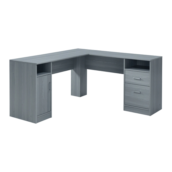
Summary of Contents for Techni Mobili RTA-8412L
- Page 1 ASSEMBLY INSTRUCTIONS Thanks for purchasing one of our products. Please read carefully the assembly instructions before the installation. Do not discard this manual or any of the packaging material until the unit has been completely assembled.
- Page 2 ▪ Left Interior panel Left Exterior panel Right Interior panel Right Exterior panel Center-Left panel Center-Right panel Left-Top Shelf panel Right-Top Shelf panel Left-Bottom Shelf Right-Bottom Shelf Left Horizontal Back Left Adjustable panel panel panel panel Top Drawer Front panel Right Horizontal Back Left Door Top Drawer Left panel...
-
Page 3: Main Parts Layout
▪ MAIN PARTS LAYOUT (For reference): ▪ HARDWARE Handle U Shape PART QTY. ITEM 3Sets (96mm) M3.6x22mm Screw 2Pcs Long Wooden Pin Door Hinge Set 2Sets (Both parts come 60Pcs Short Wooden Pin joined together) 2Pcs L Bracket Cam Lock & 16Sets Bolt Sets 4Pcs... - Page 5 ▪ Install 60pcs of Wooden Pins (2) into all panels as shown. Use a wooden or light rubber hammer to avoid damage to the pins. Please pay attention to the correct holes to use as other holes on the panels are intended for other hardware in other steps.
- Page 6 x 16 - Install bolts (3) into panels (A), (B), (S1) and (T1) in the holes indicated in the illustration. Please pay attention to the correct holes to use as other holes on the panels are intended for other , and attach the metal plates (18) using screws (7) as shown.
- Page 7 "L" Shaped Flat Shaped Separate the 4 pieces of the sliders (20) according to their shape: - The flat shaped will be used in the next step (2 pieces, both left and right). - The “L” shaped will be used until step 21 (2 pieces, left and right). Install the flat shaped sliders (20) on panels (E) and (F) using screws (4) as shown.
- Page 8 - Assemble the panel (H) to panel (Q) using screw (9) as shown. This illustration shows the same parts from step 7, but viewed from a different angle (from the right). ▪ Assemble the panel (E) to panel (Q) using screws (9) as shown.
- Page 9 This illustration shows the same parts from step 8, but viewed from a different angle (from the left). - First assemble the panels (L) and (N) to panel (E) using screws (9), then join panels (J) to panel (E) by just pushing the pins into the holes.
- Page 10 - Assemble the panel (G) to panel (P) using screw (9) as shown. This illustration shows the same parts from step 11, but viewed from a different angle (from the left). - Assemble the panel (D) to panel (P) using screw (9) as shown.
- Page 11 This illustration shows the same parts from step 12, but viewed from a different angle (from the right). - First assemble the panels (K) and (M) to panel (D) using screws (9), then join panels (I) to panel (D) by just pushing the pins into the holes.
- Page 12 This illustration shows the parts assembled in step 10 and 14 in normal upright position. - First place the parts assembled in steps 10 and 14 in the position shown in the illustration, and assemble panel (H) to panel (G) using screws (9). Then slide the panel (V) into the groves of (C) and (D), and (W) into the groves of (E) and (F).
- Page 13 First make sure that the back edge of the tabletop (B) align with the edge of the tabletop (A), then using screws (7), and from underneath the unit, attach: - The metal plate (18) from (A) to (B). - The L Brackets (16) from (P) to (A) and from (Q) to (B). This illustration shows the parts same parts from step 17, but viewed from behind.
- Page 14 - Using cam locks (3), and as shown and explained in page 4, assemble: - The side panels (S2) and (S3) to front panel (S1). ▪ Assemble the drawers back panels (S4) - The side panels (T2) and (T3) to front panel (T1). and (T4)to their respective drawers using Then insert the bottom panels (U) into the groves screws (8) as shown.
- Page 15 - Install Handle Sets (14) to door (R) , then install Hinges (15) with screw (5) as shown above. - Assemble the door (R) to the desk using screws (5) as shown and adjust the alignment if necessary: (A): These screws adjust the vertical alignment.
- Page 16 Cover all the screw heads with caps (11) as shown. DONE! Before you start using the unit, make sure that all the screws, bolts, cam locks, etc. are properly tightened, and read all the warnings in the next page. Enjoy your new unit!
- Page 17 50Kg (110 Lbs) 50Kg (110 Lbs) 5Kg (11 Lbs) 5Kg (11 Lbs) 5Kg (11 Lbs) 4.5Kg (10 Lbs) 4.5Kg (10 Lbs) 5Kg (11 Lbs)
Need help?
Do you have a question about the RTA-8412L and is the answer not in the manual?
Questions and answers