Advertisement
Quick Links
Advertisement

Subscribe to Our Youtube Channel
Related Manuals for Techni Mobili RTA-8413L


Summary of Contents for Techni Mobili RTA-8413L
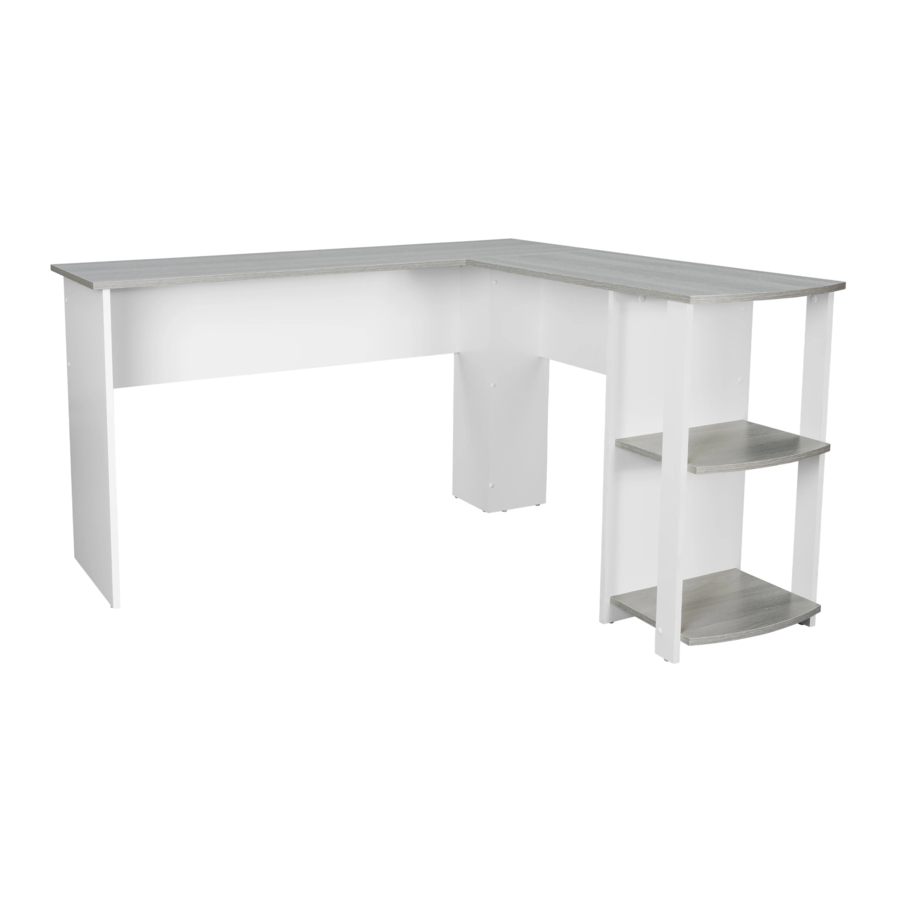
- Page 1 MODEL RTA-8413L ASSEMBLY INSTRUCTIONS Thank you for purchasing our product REV.042021-1...
- Page 2 RTA-8413L Please read carefully the assembly instructions • before the installation. Do not discard this manual or any of the packaging • material until the unit has been completely assembled. Might require two people. •...
- Page 3 RTA-8413L Right Tabletop Left Tabletop Left panel D Right Panel Center-Left Panel Center-Right Panel Right Shelf Panel Shelf Left Support Left Back panel Right Back panel Adjust panel Shelf Right Support MAIN PARTS LAYOUT (FOR REFERENCE)
- Page 4 RTA-8413L LIST OF HARDWARE, SCREWS AND FITTINGS PART QTY. ITEM 2Pcs Long Dowel 22Pcs Short Dowel Cam Lock & 8Sets Bolt Sets 14Pcs ST 3.5 x 16 15Pcs ST5 x 40 Caps for 8Pcs Cam locks 15Pcs Screw Caps 3Pcs...
- Page 5 RTA-8413L ☛ This unit uses cam bolts and locks. The following explains how to use them. This is not an assembly step; it is a guide for when you are actually doing the assembly using this kind of hardware. Cam Bolt Cam Lock 1.
- Page 6 RTA-8413L ❼ BEFORE YOU START THE ASSEMBLY, PLEASE READ THE FOLLOWING TIPS AND WARNINGS. ❶ To avoid Do a quick inventory misalignments, always to make sure the package leave the screws loose contains all the parts and and tighten them until...
-
Page 7: Assembly Steps
RTA-8413L ASSEMBLY STEPS STEP 1 Install all the short dowels 2 into all panels as shown. Use a wooden or light rubber hammer to avoid damage to the pins. Hardware/Tools: Please pay close attention to which holes you have to use, and do not join any parts... - Page 8 RTA-8413L First install bolts 3 into the panels A and B in the holes indicated in the illustration. STEP 3 Then install the metal plate 9 on the panel B using screws 4 as shown. Hardware/Tools: Bolt ST3.5 x 16 (NOT INCLUDED) (Panels are shown upside-down).
- Page 9 RTA-8413L STEP 5 Assemble the panels D and G using screw 5 as shown. Hardware/Tools: ST5 x 40 (NOT INCLUDED) STEP 6 Assemble panel I to panel G with screw 5 making sure the big hole for the cam lock on panel I goes facing towards the inside.
- Page 10 RTA-8413L STEP 7 Flip over the pieces from step 6, and assemble the panel H to panel G with screw 5 as shown. Hardware/Tools: On panel H, the big hole ST5 x 40 for the cam lock goes facing towards the inside.
- Page 11 P.10 RTA-8413L P.10 STEP 9 Assemble the panel F to panel K using screws 5 as shown, then install the glides 10 to the bottom of the panels D, F, H and I as shown. Hardware/Tools: ST5 x 40 (NOT INCLUDED) STEP 10 Assemble the panel C to panel J using screws 5 as shown.
- Page 12 P.11 RTA-8413L P.11 STEP 11 Assemble the panel E to panel J using screws 5 as shown, then install the gildes 10 to the bottom of the panels C and E as shown. Hardware/Tools: This illustration shows the same ST5 x 40 parts from step 10, but viewed from the right.
- Page 13 P.12 RTA-8413L P.12 STEP 13 With the help of another person, place first the right tabletop B over the right section of the unit, then place the left tabletop A over the left section. Then insert Hardware/Tools: the cam locks 3 into the holes of panels C, D, E, F, H and I making sure they go aligned, and turn the cam locks as explained in page 4.
- Page 14 P.13 RTA-8413L P.13 STEP 15 Cover all the screw heads with caps 7 as shown. Insert the metal pins 11 into the corresponding holes on panels D, H and I, and place the Shelf panel L over the Hardware/Tools: pins as shown.
- Page 15 P.14 RTA-8413L P.14 ALL DONE! Give yourself a nice pat on the back. You did a great job!
-
Page 16: Weight Limits
P.15 RTA-8413L P.15 AFTER THE ASSEMBLY IS DONE, PLEASE READ CAREFULLY THE FOLLOWING CARE AND MAINTENANCE WARNINGS: WEIGHT LIMITS 110 Lbs (50Kg) 22 Lbs (10Kg) 11 Lbs (5Kg) 11 Lbs (5Kg) Do not exceed the indicated weight limits. · Do not expose the surfaces to direct sunlight or to extreme environmental conditions. - Page 17 P.16 P.16 RTA-8413L...
- Page 18 P.17 P.17 RTA-8413L...
Need help?
Do you have a question about the RTA-8413L and is the answer not in the manual?
Questions and answers