Table of Contents
Advertisement
Quick Links
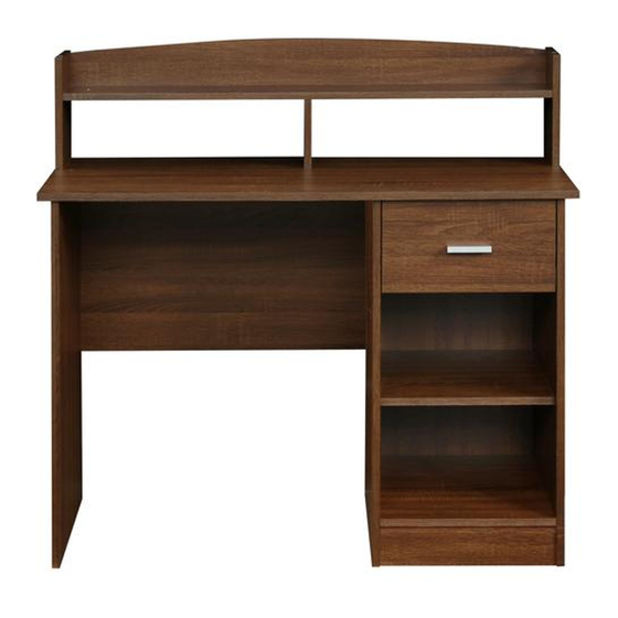
MODEL RTA-8409
ASSEMBLY INSTRUCTIONS
Thank you for purchasing one of our products.
Please read carefully the assembly instructions before the installation.
Do not discard this manual or any of the packaging material until the unit
.
has been completely assembled
MIGHT REQUIERE
OF 2 PERSONS
Imported By
Advertisement
Table of Contents

Related Manuals for Techni Mobili RTA-8409


Summary of Contents for Techni Mobili RTA-8409
- Page 1 MODEL RTA-8409 ASSEMBLY INSTRUCTIONS Thank you for purchasing one of our products. Please read carefully the assembly instructions before the installation. Do not discard this manual or any of the packaging material until the unit has been completely assembled MIGHT REQUIERE...
-
Page 2: Main Parts List
RTA-8409 MAIN PARTS LIST Hutch top panel Hutch left Hutch right Hutch middle panel panel panel Hutch horizontal panel Main panel Left panel Right panel Middle panel Bottom panel Adjustable panel Foot panel Left back panel Drawer front panel Drawer left panel... -
Page 3: Hardware List
RTA-8409 MAIN PARTS LIST Drawer right panel Drawer back panel Drawer bottom panel Right back panel HARDWARE LIST: Parts 1-13 come together; parts 14 come separate. Part Figure Description 8x25mm wooden pins (dowels) MAIN PARTS LAYOUT 15mm cam locks and bolts... - Page 4 RTA-8409 BEFORE YOU START THE ASSEMBLY, PLEASE READ THE FOLLOWING TIPS AND WARNINGS. • Do a quick inventory to make sure the product contains all the parts and hardware. • Missing, damaged and defective parts can be replaced at no cost to you. Please refer to the CONTACT card included with the product.
-
Page 5: Assembly Steps
RTA-8409 ASSEMBLY STEPS Install wooden pins (1) into panels (A), (B), (C), (D), (E), (G), (H), (I), (J), (L), (M), (O) and (P) STEP 1 in the holes shown in the illustrations. Please note that other holes on the panels are Hardware: intended for other hardware in other steps. - Page 6 RTA-8409 STEP 3 Grab the set of sliders (14) and separate the pieces According to their shape: - The “flat” ones will be used on the next step. - The “L” shaped will be used until step 19, so please set them aside.
- Page 7 RTA-8409 STEP 8 Assemble the hutch right panel Insert and align the cam lock (2) STEP 7 (C) to the hutch panels (A) and into the hutch middle panel (D), Hardware: Hardware: (E) using screws (3), and cover and assemble to panel (E) as the screws with (10) as shown.
- Page 8 RTA-8409 Assemble the middle panel (I) to the back panel (M) using screws (3) as shown. STEP 11 Hardware: M5x40mm (Panel I shown from its right side (Same parts as step 10, but with its back edge facing down) shown from the right) STEP 12 Assemble the bottom panel (J) to panel (I) using screws (3), and cover the screws with (10).
- Page 9 RTA-8409 STEP 14 Slide the right back panel (S) into the groves of the panels (I) and (H) as shown. (Same parts as step 13, but shown in normal upright position) STEP 15 First insert and align the cam locks (2) in the panels (G), (H) and (I).
- Page 10 P.10 RTA-8409 P.10 STEP 16 Insert and secure the corner brackets (12) on the 2 back corners of the unit using screws (13) as shown. Hardware: C. Bracket M3x16 (Same parts as step 15, but shown from behind) STEP 17...
- Page 11 P.11 RTA-8409 P.11 STEP 19 With the drawer upside-down and its front facing away from you, assemble the “L” shaped sliders (14) using screws (5) as shown. Hardware: M3.5x16m ATTENTION: VERY IMPORTANT! (Same parts as step 17, but shown upside-down with front...
-
Page 12: Weight Limits
P.12 RTA-8409 P.12 AFTER THE ASSEMBLY IS DONE, PLEASE READ CAREFULLY THE FOLLOWING CARE AND MAINTENANCE WARNINGS: WEIGHT LIMITS 11 Lbs. (5 Kg) 110 Lbs. (50 Kg) 11 Lbs. (5 Kg) 22 Lbs. (10 Kg) 22 Lbs. (10 Kg) • Do not exceed the indicated weight limits.
Need help?
Do you have a question about the RTA-8409 and is the answer not in the manual?
Questions and answers