
Subscribe to Our Youtube Channel
Related Manuals for Techni Mobili RTA-8400


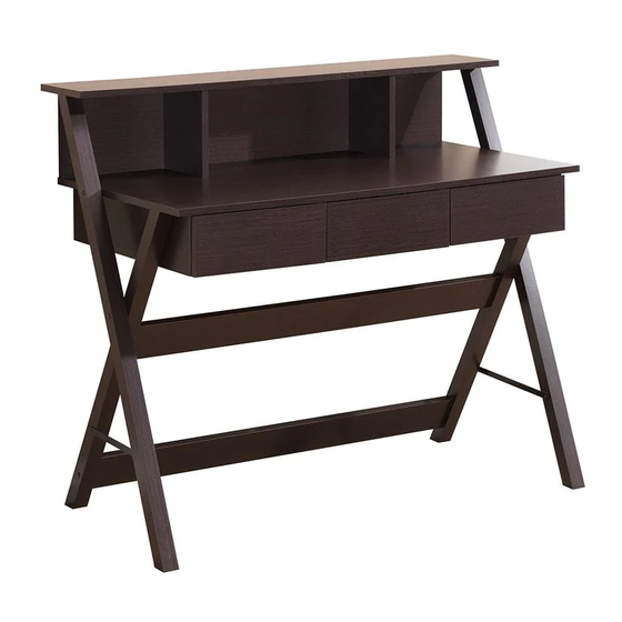
Summary of Contents for Techni Mobili RTA-8400
- Page 1 ASSEMBLY INSTRUCTIONS Thanks for purchasing one of our products. Please read carefully the assembly instructions before the installation. Please save this manual for future reference.
- Page 3 -Front-Right Leg -Back-Right Leg...
- Page 4 PART QTY. ITEM PART QTY. ITEM 56Pcs 4Pcs Wooden Pin Plastic Feet Screw - 5 x 8mm Plastic Cap 12Pcs 8Pcs (Euro Screw) 16Pcs 2Pcs Plastic Cap Screw - 3.5 x 16mm 12Pcs Screw - 4 x 38mm Right 10Pcs Screw - 5 x 38mm 3Sets Sliders...
- Page 6 Insert the wooden pins (1) into the corresponding holes on panels (C), (D), (E), (G), (H), (I), (J), (K), (L), (N), (P), (T) and (U) as shown. Please make sure to insert them in the correct holes as some holes are intended for different hardware in subsequent steps. Attach the cam bolts (8) to the corresponding holes on panels (A), (B), (G), (H), (Q), (R) and (S) as shown.
- Page 7 Assemble the FLAT sliders (12) to the panels (G), (H) and (I) using screws (2) as shown. For better orientation and correct assembly, place the panels as shown and screw the sliders first at the front used until step 14. (This view is with panel (B) upside-down) Insert and align the cam locks (8) into panels (C), (D) and (E), then assemble these panels...
- Page 8 (This view is from underneath the Main Panel (A) with its front facing UP, and panels (B/C/E/D) behind it) Assemble the Main Panel (A) to panels (C), (D) and (E) using screws (5) as shown. Assemble the panels (J) and (K) to panels (I) using screws (5) as shown. Insert and align the cam locks (8) into panels (J) and (K), then assemble the panels (G) and (H) on the sides as illustrated and as explained in page 4.
- Page 9 (This view is from underneath the unit with its front facing UP) Insert and align the cam locks (8) into the corresponding holes on panels (G), (H), (I) and (K), and assemble these panels to Main Panel (A) as illustrated and as explained in page 4. (This view is from underneath the unit with its front facing UP) First assemble very loose the Back Right Leg (P) to panel (H) and the Back Left Leg (N) to panel (G)
- Page 10 Using cam locks (8), assemble the Front-Left Leg (M) to the Top Shelf Panel (B) ON THE LEFT SIDE, and the Front-Right Leg (O) ON THE RIGHT SIDE as illustrated and as explained in page 4. Then attach the Plastic Feet (9) to the bottom of the legs as shown. Secure both legs (M) and (O) to the legs (N) and (P) and to the Main Panel (A) using screws (7) as shown.
- Page 11 (You can now place the unit in its upright position) Assemble the Metal Plates (14) to the legs on both sides of the unit using screws (3) as shown. NOTE: On the back legs screw from the OUTSIDE, on the front legs screw from the INSIDE. First assemble each of the drawer front panels (Q), (R) and (S) to the drawer side panels (T) and each of the 3 drawers as shown.
- Page 12 Left First assemble the drawer back panel (V) to each of the 3 drawers using screws (4) as shown. protrude from the bottom of the drawer, otherwise the drawer will raise about half inch more and won't fit in the unit. First insert the 3 drawers IN THE EXACT SAME ORDER SHOWN: (Q) on the LEFT, (R) on the CENTER, and (S) on the RIGHT, otherwise the drawers will overlap each other.
Need help?
Do you have a question about the RTA-8400 and is the answer not in the manual?
Questions and answers