
Related Manuals for Cincoze DS-1102-R20


Summarization of Contents
Preface
Revision History
Details changes made to the manual over different versions.
Copyright Notice
States copyright ownership and usage restrictions for the manual.
Acknowledgement
Mentions registered trademarks and product names used in the manual.
Disclaimer
Outlines the manual's purpose, limitations, and potential for errors.
Declaration of Conformity
States compliance with FCC rules for digital devices.
Product Warranty Statement
Warranty Terms
Details the 2-year warranty terms and conditions for Cincoze products.
RMA Process
Explains the Return Merchandise Authorization process for product service.
Conventions Used in this Manual
Safety Precautions
Provides essential safety guidelines for installing and using the device.
Package Contents
Ordering Information
Lists available product models and their descriptions.
Optional Modules & Accessories
Lists optional expansion modules and accessories for the product series.
Chapter 1 Product Introductions
Overview
Provides a general overview of the DS-1100 Series embedded computer.
Highlights
Summarizes key features and functionalities of the DS-1100 Series.
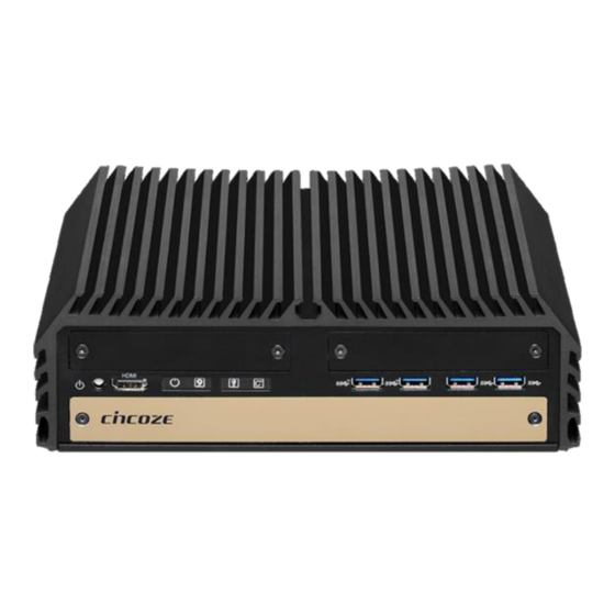
Product Pictures
Shows front and rear views of DS-1100, DS-1101, and DS-1102 models.
Key Features
Lists the main technical specifications and certifications of the DS-1100 Series.
Hardware Specification
Details the technical specifications of the system's hardware components.
System I/O
Describes the input/output interfaces and connectors on the system.
Mechanical Dimension
Displays physical dimensions and mounting information for the product series.
Chapter 2 Switches & Connectors
Location of Switches and Connectors
Identifies the physical locations of switches and connectors on the motherboard.
Switches and Connectors Definition
Provides definitions for various switches and connectors on the system.
Definition of Switches
Explains the function and settings of specific DIP switches.
Definition of Connectors
Details the pin assignments for various connectors, including Mini PCI-Express.
Chapter 3 System Setup
Removing the Top Cover
Step-by-step instructions for safely removing the system's top cover.
Installing the CPU
Guide on how to properly install the Central Processing Unit (CPU) into the socket.
Installing SO-DIMM Memory
Instructions for installing SO-DIMM memory modules into the system.
Installing a Mini-PCIe/mSATA Card
Guide for installing Mini-PCIe or mSATA cards on the system.
Installing a SATA Hard Drive
Steps for installing a 2.5" SATA HDD/SSD on the top side.
Installing a CMI Module
Procedure for installing CMI modules for expanded I/O.
Installing a PCI/PCIe Add-on Card
Guide for installing PCI or PCIe expansion cards using riser cards.
Assembling the System
Steps for reassembling the system after component installation.
Installing the CMOS Battery
Steps for replacing or installing the CMOS battery.
Wall Mount Brackets
Instructions for mounting the system to a wall using provided brackets.
Chapter 4 BIOS Setup
BIOS Introduction
Explains the purpose and basic operation of the BIOS.
Main Setup
Details the primary BIOS setup screen and navigation controls.
System Date and Time Settings
Instructions for configuring the system date and time within the BIOS.
Advanced Setup
Covers advanced system configurations and feature settings.
ACPI Settings
Settings related to Advanced Configuration and Power Interface.
AMT Configuration
Configuration options for Intel Active Management Technology.
SATA Configuration
Settings for SATA controller modes and features.
CSM Configuration
Settings for Compatibility Support Module (CSM) for legacy boot options.
USB Configuration
Settings for USB controller support and features.
Chipset Setup
BIOS settings related to the system chipset.
Security Setup
BIOS security settings, including passwords.
Administrator Password
Controls access to the BIOS Setup utility.
Boot Setup
Configuration options for system boot behavior.
Save & Exit Options
Options for saving changes, discarding changes, and exiting the BIOS setup.
Chapter 5 Product Application
Digital I/O (DIO) Application
Describes the Digital I/O (DIO) application and its programming.
Digital I/O Pins Definition
Lists and defines the pins used for Digital I/O functionality.
Digital I/O Programming Guide Details
Details the procedures for programming Super I/O chip configuration registers.
Sample Code in C Language
Provides sample C code for controlling Digital I/O pins.
DIO Hardware Specification
Details the electrical specifications for the Digital I/O hardware.
CMI-CD, CMI-ICD Connector Definition
Defines the pin assignments for CMI-CD and CMI-ICD connectors related to DIO.
Need help?
Do you have a question about the DS-1102-R20 and is the answer not in the manual?
Questions and answers