Table of Contents
Advertisement
Secret
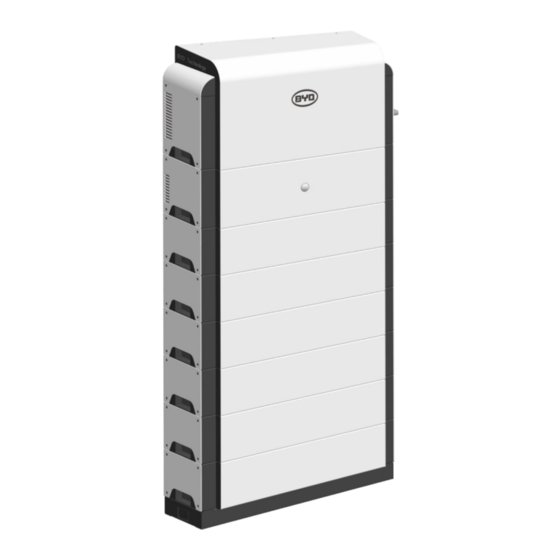
BYD Energy Pod
Household Energy Storage System
User‟s Installation and Use Manual
—————————————————————————————————————————————
Energy Pod 3kW/7.2kWh AC, Energy Pod 4kW/9.6kWh AC, Energy Pod 5kW/12kWh AC, Energy Pod 5kW/14.4kWh AC
V1.0
_____________________________________________________
Note: Please read and understand all the contents of this Manual carefully before installation and
use of the product, and please keep this Manual properly for look-up at any time.
Advertisement
Table of Contents

Subscribe to Our Youtube Channel
Related Manuals for BYD Energy Pod Series


Summary of Contents for BYD Energy Pod Series
- Page 1 Secret BYD Energy Pod Household Energy Storage System User‟s Installation and Use Manual ————————————————————————————————————————————— Energy Pod 3kW/7.2kWh AC, Energy Pod 4kW/9.6kWh AC, Energy Pod 5kW/12kWh AC, Energy Pod 5kW/14.4kWh AC V1.0 _____________________________________________________ Note: Please read and understand all the contents of this Manual carefully before installation and...
-
Page 2: Table Of Contents
Secret Table of Contents About this Manual ......................1 Description ........................1 Introduction ........................1 Nameplate ......................... 1 Safety ..........................2 Symbols ..........................2 Environmental Requirements .................... 3 Safety Requirements for Installation ................. 3 Safety Requirements for Use ..................... 4 III. -
Page 3: About This Manual
Secret I. About this Manual Thank you very much for choosing the BYD Energy Pod household energy storage system developed and produced by BYD. We sincerely believe that our products can satisfy your needs, and also look forward to your feedback on the performance of the product during use, so that we can further improve the quality of the product. -
Page 4: Safety
Manual. BYD will not be responsible for any damage to the product or personal injury caused due to any operation and usage that violates the above-mentioned relevant contents, and will no longer provide any quality assurance service. -
Page 5: Environmental Requirements
Secret 2 Environmental Requirements Do not install and use this product in an environment with temperatures below -10℃ or above 50℃ Do not install and use this product near any heat source or combustible materials Do not install and use this product in the areas where the persons frequently move ... -
Page 6: Safety Requirements For Use
III. Compliance The BYD Energy Pod product range has been designed and manufactured to comply with the requirements of the relevant Australian and New Zealand Standards The product design has been independently certified and carries the RCM marking and is listed on the Australian Government ERAC website ... -
Page 7: Product Introduction
Secret 1 Product Introduction The BYD Energy Pod is a new generation of the household energy storage system which can meet the diversified needs of the users around the world. The high- performance lithium iron phosphate battery is adopted, and the functional integration... -
Page 8: Product Composition
Secret Nominal Current 17.4A 17.4A Nominal Voltage 230Vac Nominal Frequency 50Hz(Default)/60Hz, Single phase Battery Capacity 7.2kWh 9.6kWh 12kWh 14.4kWh Battery 96Vdc/(84~108) 128Vdc/(112~144) 160Vdc/(140~180) 192Vdc/(168~216) Voltage/Range >90% Other Ingress Protection IP55 rating Dimension L* D* H 755*295*1155mm 755*295*1325mm 755*295*1490mm 755*295*1655mm Noise 40dB(A) Weight 124kg... - Page 9 Secret 3.1 PCS PCS Parameter Table: Parameter Value DC voltage range 84~216Vdc Maximum DC current 40Adc Rated AC voltage 230Vdc Maximum AC current 25Aac Rated frequency 50Hz Maximum power Maximum efficiency Operating temperature -10~50℃ Dimension 755*270*355mm Weight 31kg Connection to the grid, maximum current of GRID interface 23.8A Connection to the load, maximum current of...
- Page 10 Secret 3.2 BMS BMS Parameter Table: Parameter Value DC voltage range 60~200Vdc Maximum current 40Adc Operating temperature -10~50℃ Dimension 755*270*210mm Weight 14kg LAN interface Connection to the external ROUTER RS485-1 interface Connection to the client controller RS485-2 interface Connection to the electric meter BA Switch 63A/550Vdc 3.3 Battery...
-
Page 11: Product Functional Logic
Secret 3.4 BASE BASE Parameters Parameter Value Rated current Rated voltage 700V Dimension 730*240*165mm Weight 4 Product Functional Logic The logical relationship between functions of the product is shown in the following figure: When the power grid does not meet the conditions for grid connection, the function of emergency power supply only supports the matched load. - Page 12 Load & BYD Energy Pod Load The priority of power supply to load is as: ① Photovoltaic power supply > ② BYD Energy Pod power supply > ③ Grid power supply 5.2 Remote control The product is provided with the RS485 interface and capable of responding to the control command issued by the external controller.
-
Page 13: Monitoring
Secret Note: The system does not support the startup when the power grid is not connected. Monitoring After the Energy Pod is put into use, the user can view the status of the product through the provided website. 6.1 Open browser and type in the url: https://energycontainerdata.azurewebsites.net 6.2 Choose Language and enter the user‟s account and password in the login interface, and click Login... -
Page 14: Installation
Secret V. Installation Installation Instructions Please read and understand this part carefully before installation of product. 1.1 Personnel qualification The installer of the product shall have the local electrician qualification, have received the safety and technical training, obtain the qualification authorized for the installation of the product, possess the experience in installation and use of electrical equipment, and the following capabilities, including but not limited to: ... -
Page 15: Location
2 Location An appropriate location should be considered before installing BYD Energy Pod. 2.1 Location restrictions in Australia Local or National restrictions may prohibit installation in some locations. In Australia, AS5139 provides guidance as to where a Battery Energy Storage System (BESS) cannot be installed. - Page 16 In areas of traffic that may result in physical damage to the BYD Energy Pod unit or where the installation of BYD Energy Pod unit would restrict entry or egress. In areas where temperatures will exceed 50°C (noting that performance will be ...
-
Page 17: Installation Preparations
2.5 AS3000 – Mechanical Protection AS/NZS 3000 requires that adequate mechanical protection be installed to prevent damage to the BYD Energy Pod in any areas where the equipment may be struck and damaged (for instance in a garage). Any Bollards used to provide mechanical protection should located such that they do not interfere with access to the Energy Pod unit for service, inspection or maintenance. - Page 18 Secret Insulated gloves: ensure the life safety of installers Safety shoes: ensure the safety in case of accidental falling of modules during installation 3.3 Unpacking and accessories The product is composed of multiple modules, the PCS and Battery are packed separately, the BASE and BMS are packaged in one package, and each component is distinguished according to the external labels of the package.
- Page 19 Secret Graphical Accessories Qty. Function expression Connection of Load Load connector with PCS Exploded view of waterproof connector: 3.3.2 BMS&BASE ■ Label: P.R. BASE& BMS G.W. ___kg 800345390mm ■ Unpacking: ■ Accessories: Accessories Graphical expression Qty. Function Wall hanging accessory Fixation of BMS Wall hanging accessory Fixation of BMS...
-
Page 20: Formal Installation
Secret designed to be fixed on the wall, and comprised of the wall hanging accessory 1 installed at the rear of BMS and the wall hanging accessory 2 installed on the wall. 3.3.3 Battery ■ Label: P.R. BATTERY G.W. ___kg 800345250mm ■... - Page 21 Secret Hole drilling distance on wall 450/500/600 Vertical spacing of fixing holes of base Transverse spacing of fixing holes of base Transverse distance between fixing hole of wall hanging accessory and fixing hole of base Distance between fixing hole of base and wall surface d Hole diameter...
- Page 22 Secret 4.3 Installation of wall hanging accessory 2 and BASE Take off the nuts and washers of the expansion bolts in 4.2, install the wall hanging accessories and base at the corresponding positions, and tighten the nuts with a torque of 45N.m. The limiting stopper is designed at the rear of the base. 4.4 Installation of modules The Battery, BMS and PCS are installed in sequence, and are fixed with each other by use of bolts.
- Page 23 Secret ■ Installation of BMS and PCS Install the BMS and PCS in sequence, and insert the wall hanging accessory 1 at the rear of the BMS into the hole of the wall hanging accessory 2 on the wall ※Note: Each part shall be handled with care during installation, in order to avoid damage to the components.
- Page 24 Secret 4.6 Installation of fuse Remove the fuse cover plate on the base by use of the Phillips screwdriver, install the fuse at the corresponding position, and then reinstall the cover plate. The fuse may be installed only after completion of installation of all contents, in order to avoid the electric shock.
- Page 25 Secret 4.7.1 Cable specification requirements The following table shows the information about cables recommended for the Energy Pod. Please ensure that the correct cable is used for wiring: Item Description Cable specification L:Brown 10AWG Connection from Grid interface of Grid N:Blue 10AWG Energy Pod to power grid PE:Yellow&Green 10AWG...
- Page 26 Secret ■ Connect the stripped power grid wire into the terminal slot of the corresponding connector, and tighten the screw (Note: the screw shall be in direct contact with the wire core, the wire skin cannot be used for fixing, and the wire core exposed outside the terminal slot shall not exceed 1/2 of the insulation blocking wafer).
- Page 27 Secret 35~40mm 8.51mm ■ Connect the stripped load wire into the terminal slot of the corresponding connector, and tighten the screw (Note: the screw shall be in direct contact with the wire core, the wire skin cannot be used for fixing, and the wire core exposed outside the terminal slot shall not exceed 1/2 of the insulation blocking wafer).
- Page 28 Secret 4.7.4 CT wiring The schematic diagram of CT is shown in the left figure, and the bottom view of CT is shown in the right figure; the direction is KL, representing from GRID/PV Inverter to PCS. ■ Grid-CT The installation position and direction of CT at the end of the Grid are shown as follows.
- Page 29 Secret ■ PV-CT The installation position and direction of CT at the end of the PV are shown as follows. Insert the CT correctly connected to the PV into the corresponding CT-PV interface of the PCS. Note: The length of network cable accompanied with the CT is 3m. If the cable is not long enough, the user need to prepare the network cable with sufficient length and use the network cable connectors to connect the CT with the CT interface on PCS.
- Page 30 Secret 4.7.5 LAN wiring: ■ Connect the cable connected to the ROUTER into the BMS LAN interface. 4.7.6 RS485 wiring: ■ The RS485 interface is an external communication interface, through which the control commands can be issued to the system. The RS485 interface is defined as follows.
-
Page 31: Check And Confirmation
Secret 5 Check and Confirmation Prior to officially using the product, please check each item listed in the table one by one according to the Check and Conformation Form given below, including product fixation, electrical connection, etc. Check and Confirmation Form Items Confirmation Base fixing bolts... -
Page 32: Installation Submission
Secret Status description Indicator Status Light up The product is in startup and running state. Light out The product is in shutdown state. Twinkle The product is in fault state. Note: The product cannot be started up in case that the power grid is not connected. -
Page 33: Induction And Training Of The System Owner/Operator
Owner/Operator of the equipment. Instruction should cover site-specific details, safety and methods of operation. The BYD Energy Pod ships with a separate Owner‟s Manual. Be sure to pass the Owner‟s Manual to the new owner and direct them to read the contents. -
Page 34: Frequently Asked Questions And Maintenance
Secret The Power Button on the front of the unit. The MCB protecting the Normal circuit and the EPS circuit. Any relevant switches, MCBs or other isolators used in the Backup Circuit. Show the owner the location of the Shutdown Procedure labels. VI. - Page 35 Secret Code Fault Item 15205 Serious low temperature 15206 Serious overcurrent for charging 15207 Serious overcurrent for discharging 15208 Out-of-limit of charging current 15209 Out-of-limit of discharging current 15210 Startup failure _ Precharge not full 15211 Stop failure _ Current unsafe 15212 Serious electric leakage 15215...
-
Page 36: Cleaning
Secret Code Fault Item 35105 Branch current 1 sampling failure 35106 Branch current 2 sampling failure Input voltage sampling failure at the 35107 side of battery 35108 Output voltage sampling failure Radiator temperature sampling 35109 failure DC1 Inductor temperature sampling 35110 failure DC2 Inductor temperature sampling... -
Page 37: Quality Assurance
VII. Quality Assurance After the product is installed and put into use, BYD will start to provide the quality assurance service according to the BYD Energy Pod User's Installation and Use Manual and the Energy Pod Warranty Letter of BYD Auto Industry Company Limited. -
Page 38: Contact Us
Secret VIII. Contact Us For any assistance about BYD product, please contact BYD by: Electric Power Research Institute BYD Auto Industry Company Limited / BYD Lithium Battery Co., Ltd No.3009, BYD Road, Pingshan, Shenzhen, 518118, P.R.China Tel:+86 0755-89888888 - 57860...
Need help?
Do you have a question about the Energy Pod Series and is the answer not in the manual?
Questions and answers