BYD B-BOX 2.5 Installation Manual
Hide thumbs
Also See for B-BOX 2.5:
- Installation guidance (43 pages) ,
- User manual (20 pages) ,
- Installation guidance (38 pages)
Table of Contents
Advertisement
Quick Links
Download this manual
See also:
User Manual
Advertisement
Table of Contents

Related Manuals for BYD B-BOX 2.5


Summary of Contents for BYD B-BOX 2.5
- Page 1 B-Box Professional installation guidance Installation Guidance B-Box Pro2.5~10.0 Rev 2.1_Jul.2017 1/ 38...
-
Page 2: Table Of Contents
B-Box Professional installation guidance Content Safety ........................................4 1 Product Overview ....................................5 2 Cabinet terminal introduction ................................6 3 Cable outlet of cabinet ..................................7 4 B-Plus2.5 interface and terminal introduction ..........................8 5 Preparations ......................................10 5.1 Installation notice ..........................................10 5.2 Package information and system configuration list .............................. - Page 3 B-Box Professional installation guidance Appendix 2 ......................................38 Installation Video Website: http://www.byd.com/energy/b-box-25.htm 3/ 38...
-
Page 4: Safety
Ensure reliable grounding. Do not reverse the front panel. CAUTION: Due to the heavy weight of BYD B-Box 2.5~10.0, please use strong packaging and safety protection equipment during transportation, to ensure safety and avoid accidental damage. When increase battery, power off the battery and other power input first. -
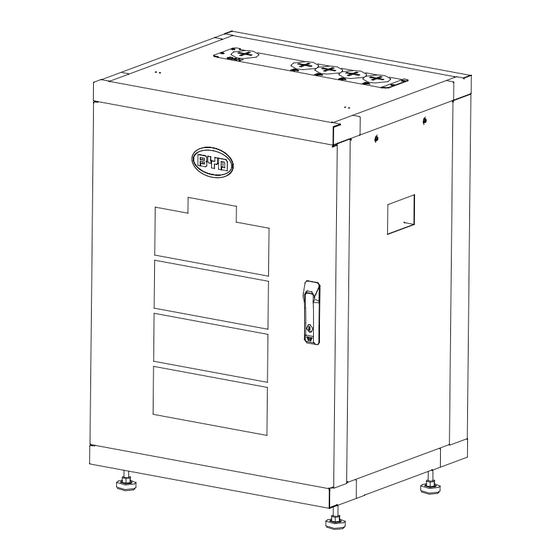
Page 5: Product Overview
B-Box Professional installation guidance 1 Product Overview BYD battery box products B-Box Pro 2.5~10.0 as the energy storage parts can be used in off-grid & on-grid energy storage system. Internal view of B-BOX Overview of B-BOX 5/ 38... -
Page 6: Cabinet Terminal Introduction
B-Box Professional installation guidance 2 Cabinet terminal introduction ① ⑤ ③ ④ ⑥ ② ⑧ ⑨ ⑩ Terminal list Interface Mark Function Connect to battery in cabinet, each terminal can connect 1~2 battery Connect to battery in cabinet ... -
Page 7: Cable Outlet Of Cabinet
B-Box Professional installation guidance 3 Cable outlet of cabinet Compare list Interface Mark Function CAN communication cable Positive cable from another B-BOX Positive cable from inverter Negative cable from inverter Negative cable from another B-BOX 7/ 38... -
Page 8: Plus2.5 Interface And Terminal Introduction
B-Box Professional installation guidance 4 B-Plus2.5 interface and terminal introduction P-:Negative terminal P+:Positive terminal GND:Grounded terminal 8/ 38... - Page 9 B-Box Professional installation guidance Table 1 Display and communicate interface Interface Mark Function SOC LED Indicates State of capacity of battery RUN LED Indicates the B-Plus is running status ERR ADDR Indicates error status Alarm Indicates alarm status ...
-
Page 10: Preparations
B-Box Professional installation guidance 5 Preparations 5.1 Installation notice a) Battery installation location should be away from heat sources and sparks should be avoided. The safety distance should be more than 0.5m. b) Battery connection cables should be as short as possible, to prevent excessive line pressure drop. c) Batteries with different capacity, different P/N or different manufacturers are not allowed for connection. -
Page 11: Package Information And System Configuration List
B-Box Professional installation guidance 5.2 Package information and system configuration list The cabinet and battery are packaged separately with cartons, the components are supplied with the cabinet or battery package. Before installation, installers should read the system configuration list. Item Description Purpose Picture Anchor bolt... - Page 12 B-Box Professional installation guidance 5.3 Configuration list Type B-BOX 2.5 B-BOX 5.0 B-BOX 7.5 B-BOX 10.0 B-Box cabinet B-Plus2.5 User manual Positive cable Negative cable Communicate cable Grounded cable 12/ 38...
-
Page 13: Installation Tools
B-Box Professional installation guidance 5.4 Installation Tools Cross screwdriver Flat tip screwdriver Sockets spanner M3~M10 M3~M6 Diagonal cutters Adjustable wrench Knife 5.5 Personal protective equipment 13/ 38... -
Page 14: Installation
B-Box Professional installation guidance 6 Installation 6.1 Opening the package Tools: Knife 向上 易碎物品 怕雨 堆码层数极限 LITHIUM ION BATTERIES UN3480 4G/Y50/S/16 CN/XXXXXX PI:XXX 14/ 38... -
Page 15: Disassembling The Pallet & Anchor Bolt Installation
B-Box Professional installation guidance 6.2 Disassembling the pallet & anchor bolt installation Tools: Adjustable spanner fixed torque: 10±1 Nm Lay down the cabinet, put some Take away the pallet and four protections on the ground to avoid screws that installed on the root of sratches. -
Page 16: Battery Installation
B-Box Professional installation guidance 6.3 Battery installation Tools: Cross screwdriver Move the cabinet to the installation Open the door, take away the screws of Fix all batteries with screws. place, prepare to install battery. the battery storey and front panel. Finish battery installation. -
Page 17: Connection Of Cables
B-Box Professional installation guidance 6.4 Connection of cables Tools: Cross screwdriver Remove the left side panel. Tie the cable tight and pass the cables through the holes next to the batteries. Install the cables, install the positive cable to B+ DC BUS, install the negative to B- DC BUS. -
Page 18: Battery Address Set Up
B-Box Professional installation guidance 7 Battery address set up 7.1 “ADDR” switch introduction Function: For communication between battery and BMU. BMU will communicate with external equipment by using CAN communication. Each DIP switch definition: There are 6 bit switches, keep the switch on down side means”0”, turn up the switch to “ON” means “1”. Address: 000000 Address:100000 For example: when two battery in using, “ADDR”... -
Page 19: Battery Address Setting List (From 1~32 Batteries)
B-Box Professional installation guidance 7.2 Battery address setting list (from 1~32 batteries): Battery No. Address Battery No. Address 100000 100010 010000 010010 110000 110010 001000 001010 101000 101010 011000 011010 111000 111010 000100 000110 100100 100110 010100 010110 110100 110110 001100 001110 101100... -
Page 20: Connection To Inverter
B-Box Professional installation guidance 8 Connection to inverter 8.1 CAN cable connection RJ45 PIN define B-BOX GOODWE SOLAX VICTRON CAN H CAN L When installers attempt “CAN” ports connections between B-Box and inverter, please refer to below drawing. 20/ 38... -
Page 21: Power Cable Connection
B-Box Professional installation guidance 8.2 Power cable connection Tools: Cross screwdriver, fixed torque: 25±2.5Nm Remark: Each rack’s negative cables should be fastened with the belt, and the cable length between each cabinet and inverter shall be the same. Be careful not to reverse connection. -
Page 22: Starting System
B-Box Professional installation guidance 9 Starting system Notice: Before activating the system, please make sure that you: Confirm all the batteries are powered OFF. Confirm all power cables are connected correctly and securely. Confirm all communication cables are connected correctly and securely. 9.1 System activating procedures when B-Box connect to SMA Sunny Island ⑴... - Page 23 B-Box Professional installation guidance Status(display interval 2S) Definition LED(BMU) Blinks 1 time Inverter not connected Blinks 2 time Battery not connected Blinks 3 time Battery disconnected Blinks 4 time Battery failure Remark: Slow blink: indicator light is on and off every 1s (0.5Hz). Fast blink: indicator light is on and off every 0.25s (2HZ) SOC status and indicate Item...
-
Page 24: System Activating Procedures When B-Box Connects To Goodwe Inverter
B-Box Professional installation guidance 9.2 System activating procedures when B-Box connects to GOODWE inverter ⑴ Download the APP on user’s cell phone and open the home page; ⑵ Start B-Box; Press the “ON/OFF” button on front panel of B-Plus2.5; Tips: Press one second will start the B-Plus; Once start, the LED lights of B-Plus 2.5 will flash in various forms according to the battery status, as below: LED status when normal start Item... - Page 25 The last one light is normally on Capacity is 24%-1% (including) ⑶ Go to the home page of the APP, enter into the Battery Settings page, select “BYD B-BOX” battery, then select “NEXT” until the last page, finally select “Start”.
-
Page 26: System Activating Procedures When B-Box Connects To Victron Inverter
B-Box Professional installation guidance 9.3 System activating procedures when B-Box connects to Victron inverter ⑴ Start inverter; Set the battery DOD at a minimum of 5% on-grid Set the battery DOD at a minimum of 10% off-grid. ⑵ ⑶ Start B-BOX; Press the “ON/OFF”... - Page 27 B-Box Professional installation guidance Remark: Slow blink: indicator light is on and off every 1s (0.5Hz). Fast blink: indicator light is on and off every 0.25s (2HZ) SOC status and indicate Item Status Indicate Four lights are all normally on Capacity is 100%-75% (including) The last three lights are normally on Capacity is 74%-50% (including)
-
Page 28: System Activating Procedures When B-Box Connects To Solax Inverter
B-Box Professional installation guidance 9.4 System activating procedures when B-Box connects to Solax inverter ⑴ Start B-Box Press the “ON/OFF” button on front panel of B-Plus 2.5; Tips: Press one second will start B-Plus; Once start, the LED lights of B-Plus 2.5 will flash in various forms according to battery status, as below: LED status when normal start Item Status... - Page 29 B-Box Professional installation guidance SOC status and indicate Item Status Indicate Four lights are all normally on Capacity is 100%-75% (including) The last three lights are normally on Capacity is 74%-50% (including) The last two lights are normally on Capacity is 49%-25% (including) The last one light is normally on Capacity is 24%-1% (including) (2) Activate inverter;...
-
Page 30: Stopping System
B-Box Professional installation guidance 10 Stopping system Note: 1. Before stopping the system, shut down the system in the following orders: AC Load=>PV=>Inverter=>Battery 2. After stopping the system, please ensure that you: Confirm all the batteries are powered OFF. Check all the LEDs are OFF. Check that the inverter has powered off. -
Page 31: Appendix 1
B-Box Professional installation guidance Appendix 1 SMA charger min capacity Parameter setup for B-BOX2.5 Charging the battery - usage through battery backup system without increased self-consumption Parameters Setup value 003.07Batt Typ Li Lon_Ext-BMS 003.10Batt Cpynom 262.01ProtResSOC 262.02BatResSOC Charging the battery - usage through battery backup system with increased self-consumption Parameters Setup value 003.07Batt Typ... - Page 32 B-Box Professional installation guidance 262.04PVResSOC 262.03BUResSOC 262.05MinSlfCsmpSOC Parameter setup for B-BOX 5.0 Charging the battery - usage through battery backup system without increased self-consumption Parameters Setup value 003.07Batt Typ Li Lon_Ext-BMS 003.10Batt Cpynom 262.01ProtResSOC 262.02BatResSOC Charging the battery - usage through battery backup system with increased self-consumption Parameters Setup value 003.07Batt Typ...
- Page 33 B-Box Professional installation guidance 262.04PVResSOC 262.03BUResSOC 262.05MinSlfCsmpSOC Parameter setup for B-BOX7.5 Charging the battery - usage through battery backup system without increased self-consumption Parameters Setup value 003.07Batt Typ Li Lon_Ext-BMS 003.10Batt Cpynom 262.01ProtResSOC 262.02BatResSOC Charging the battery - usage through battery backup system with increased self-consumption Parameters Setup value 003.07Batt Typ...
- Page 34 B-Box Professional installation guidance 262.04PVResSOC 262.03BUResSOC 262.05MinSlfCsmpSOC Parameter setup for B-BOX10.0 Charging the battery - usage through battery backup system without increased self-consumption Parameters Setup value 003.07Batt Typ Li Lon_Ext-BMS 003.10Batt Cpynom 262.01ProtResSOC 262.02BatResSOC Charging the battery - usage through battery backup system with increased self-consumption Parameters Setup value 003.07Batt Typ...
- Page 35 B-Box Professional installation guidance 262.04PVResSOC 262.03BUResSOC 262.05MinSlfCsmpSOC Parameter setup for B-BOX in off-grid Protection for the Battery Parameters Recommended Value 223.05 BatPro1Soc 223.06 BatPro2Soc 223.07 BatPro3Soc Gen Autostart Control Parameters Recommended Value 235.03 GnSocTm1Str 235.04 GnSocTm1Stp 35/ 38...
- Page 36 B-Box Professional installation guidance Parameter setup for B-BOX7.5 Three-phase Charging the battery - usage through battery backup system without increased self-consumption Parameters Setup value 003.07Batt Typ Li Lon_Ext-BMS 003.10Batt Cpynom 262.01ProtResSOC 262.02BatResSOC Charging the battery - usage through battery backup system with increased self-consumption Parameters Setup value 003.07Batt Typ...
- Page 37 B-Box Professional installation guidance Parameter setup for B-BOX10.0 Charging the battery - usage through battery backup system without increased self-consumption Parameters Setup value 003.07Batt Typ Li Lon_Ext-BMS 003.10Batt Cpynom 262.01ProtResSOC 262.02BatResSOC Charging the battery - usage through battery backup system with increased self-consumption Parameters Setup value 003.07Batt Typ...
- Page 38 B-Box Professional installation guidance Appendix 2 Solax charger min capacity Product Min capacity B-BOX 2.5 B-BOX 5.0 B-BOX 7.5 B-BOX 10.0 B-BOX 12.8 38/ 38...
Need help?
Do you have a question about the B-BOX 2.5 and is the answer not in the manual?
Questions and answers