Table of Contents
Advertisement
Quick Links
PN# 500-10440
Rev. A.4, 12/01
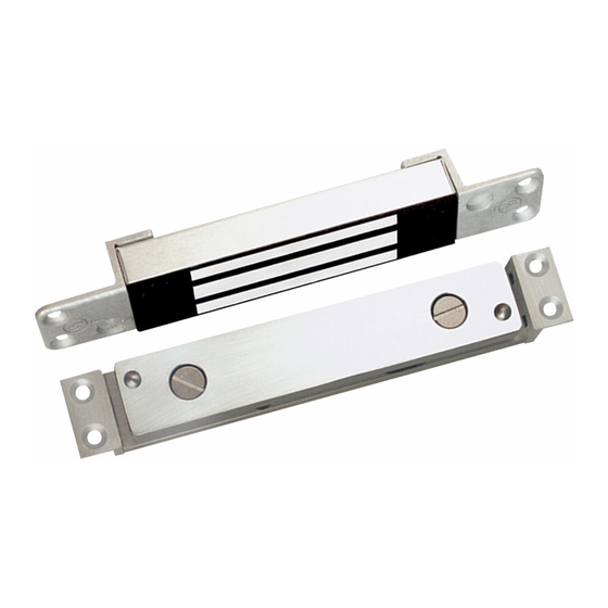
SECURITRON MODEL SAM, SAM2 SHEAR ALIGNING MAGNALOCK
TABLE OF CONTENTS AND GUIDE TO THIS MANUAL
There are two Shear Aligning Magnalock families and several different installation variables
exist for them. Accordingly, this manual provides a broad range of information- only some of
which is applicable to any individual use. This manual guide provides a brief summary of many
of the Sections which allows you to consult only the portions of the manual that apply to your
application.
SECTION 1. DESCRIPTION --------------------------------------------------------------------Page 1
SECTION 2. PHYSICAL INSTALLATION ---------------------------------------------------Page 1
SECTION 2.1. SURVEY --------------------------------------------------------------------------Page 1
SECTION 2.2 MOUNTING THE MAGNET BODY-----------------------------------------Page 3
Determine which type of door frame exists for your application and refer to the applicable
choice out of the following three Sections below.
SECTION 2.2.1 HOLLOW ALUMINUM DOOR FRAME MOUNTING ----------------Page 4
SECTION 2.2.2 HOLLOW METAL DOOR FRAME MOUNTING ----------------------Page 4
SECTION 2.2.3 SOLID WOOD DOOR FRAME MOUNTING---------------------------Page 5
SECTION 2.3 STRIKE PLATE MOUNTING ------------------------------------------------Page 6
Determine which type of door exists for your application and refer to the applicable choice
out of the following six Sections below.
SECTION 2.3.1 ALUMINUM DOOR MOUNTING WITH FLUSH TOP ---------------Page 6
SECTION 2.3.4 HOLLOW METAL (STEEL) DOOR MOUNTING ---------------------Page 8
SECTION 2.4 FINAL ADJUSTMENT OF THE STRIKE LEVEL -----------------------Page 10
This section explains the vital issue of setting the final gap between the magnet body
surface and strike plate surface. It must be studied to produce a reliable installation.
SECTION 2.5 MOUNTING ON MOTORIZED BI-PARTING DOORS-----------------Page 11
This is a special application of the SAM's on a door type that exists on many retail stores.
SECTION 3 ELECTRICAL INSTALLATION ------------------------------------------------Page 11
SECTION 3.1 GENERAL ELECTRICAL CHARACTERISTICS -----------------------Page 11
Copyright, 2001, all rights reserved • Securitron Magnalock Corp., 550 Vista Blvd., Sparks NV 89434, USA
Tel: (775) 355-5625 • (800) MAGLOCK • Fax: (775) 355-5636 • Website: www.securitron.com
An ASSA ABLOY Group company
Advertisement
Table of Contents


Need help?
Do you have a question about the Securitron Shear Aligning Magnalock SAM Series and is the answer not in the manual?
Questions and answers