Assa Abloy Securitron Magnalock Series Installation Instructions Manual

Assa Abloy Securitron Magnalock Series Installation Instructions Manual

Advertisement

MAGNALOCK MODELS M32, M62 AND M82B
1. INTRODUCTION
The Securitron Magnalock family represents the state of the art in electromagnetic locking.
There are three (3) models with operational electrical characteristics including mounting
configuration options addressed in this manual.
The BondSTAT "B" Magnalock Series, Bond Sensor, monitors the magnetic field. An internal
sensor activates a SPDT dry contact relay connection designed for interface to access control
and/or alarm systems for reporting the status of the Magnalock. (Section 5.2.4)
The DPS "D" Magnalock Series, Door Position Sensor, is activated by a special magnetic strike
armature assembly. The isolated SPDT reed switch, with an internal resettable protection device,
is designed for interface to access control and/or alarm system for door status. (Section 5.2.4)
2. SPECIFICATIONS
MODEL
Holding Force
Dimensions: Length
Height
Depth
Dual Voltage
Current: @ 12 VDC
@ 24 VDC
Capacitance: @ 12 VDC
@ 24 VDC
BondSTAT Rating
DPS Rating
3. PRODUCT OVERVIEW
Upon unpacking this product, an inventory should be made to ensure that all the required
components and hardware have been included.
installation template, the lock assembly should include the following items:
Magnalock
Strike Plate
© Copyright, 2008, all rights reserved
Securitron Magnalock Corp.
550 Vista Boulevard
Sparks, NV 89434
INSTALLATION INSTRUCTIONS
M32
600 Lbs [272 kg]
8" [203mm]
1.88" [48mm]
1.6" [41mm]
300mA
150mA
6.8 mF
6.8 mF
Voltage: 30 VDC (Maximum) ~ Current: 1 Amp (Maximum)
Voltage: 30 VDC (Maximum) ~ Current: 125 mA (Maximum)
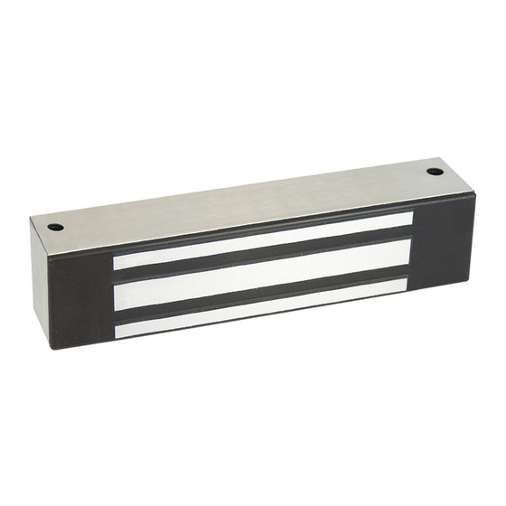
Figure 1
Page 1
Tel 775.355.5625
ASSA ABLOY, the global leader
Fax 775.355.5633
in door opening solutions
info@securitron.com
www.securitron.com
M62
1200 Lbs [544 kg]
8" [203mm]
3" [76mm]
1.75" [44mm]
12/24 Volts DC
250mA
150mA
44 mF
11 mF
Along with these instructions and the
Sex Bolt
Hardware Pack
M82B
1800 Lbs [816 kg]
12" [305mm]
3" [76mm]
1.75" [44mm]
350mA
200mA
44 mF
11 mF
PN# 500-10420
Rev. E, 05/08

Advertisement

Table of Contents
loading
Need help?

Need help?

Do you have a question about the Securitron Magnalock Series and is the answer not in the manual?

Questions and answers

Subscribe to Our Youtube Channel

Summary of Contents for Assa Abloy Securitron Magnalock Series

  • Page 1 Securitron Magnalock Corp. Tel 775.355.5625 ASSA ABLOY, the global leader 550 Vista Boulevard Fax 775.355.5633 in door opening solutions Sparks, NV 89434 info@securitron.com www.securitron.com MAGNALOCK MODELS M32, M62 AND M82B INSTALLATION INSTRUCTIONS 1. INTRODUCTION The Securitron Magnalock family represents the state of the art in electromagnetic locking.
  • Page 2: Recommended Tools

    4. RECOMMENDED TOOLS Power Drill Hammer Wire Strippers/Cutter 1/8”, 3/8”, 1/2” Drill Bits Center Punch Crimp Wire Connectors 1/2” Open end or Crescent Wrench Masking Tape Crimp Tool 3/16” Hex Key (Allen Wrench) Fish Tape or Lead Wire Multimeter 5. INSTALLATION INSTRUCTIONS Pre-Installation Survey It is recommended that an initial on sight survey be performed.
  • Page 3 5.2.1 Mounting the Strike Plate The strike plate should be mounted prior to the magnet in out-swinging door applications. Figure 3 below illustrates a typical strike mounting configuration. Door Frame & Stop 2-3 Washers Strike Mounting Strike Plate Screw 2X Roll Pins Strike Bushing 2X Roll Pin Bushings Sex Bolt...
  • Page 4 Figure 4 below illustrates a typical Magnalock out-swinging door installation. Blind Nuts Door Frame & Stop ASB Bracket (Not Included) Magnalock Flat Washers Mounting Screws Mounting Hole Dress Plugs Figure 4 Blind nuts MUST be used for mounting Magnalocks to aluminum and/or hollow metal frames. These items are included with the Magnalock hardware pack.
  • Page 5 5.2.4 Lock/Strike Installation for “B” and “D” Magnalocks IMPORTANT! PLEASE READ AND APPLY THIS INFORMATION WHEN ALIGNING/INSTALLING THE LOCK AND STRIKE. THE ALIGNMENT TOLERANCES INDICATED FOR EACH LOCK MODEL ARE CONSIDERED CRITICAL FOR THE PROPER OPERATION OF BOTH THE MAGNETIC BOND SENSING AND DOOR POSITION SENSING SYSTEMS! SENSOR RANGES (PHYSICAL POSITIONING): The BondSTAT “B”...
  • Page 6 5.2.5 Single Lock - Double Door Magnalock Mounting A single Magnalock can be used to secure double doors using a split strike plate. The part numbers reduction of holding force for each model is listed below in Table B. Use the template and instructions provided with the split strike package for proper installation.
  • Page 7: Electrical Installation

    GATE STYLE OPERATIONS AND INSTALLATION TECHNIQUES Figure 9 ELECTRICAL INSTALLATION 5.3.1 General Characteristics The Magnalock is a low current load device using specialized internal circuitry. The normal characteristic of an inductive load, such as inductive kick-back, is not present. See Section 2 for more information.
  • Page 8 5.3.5 Electrical Wiring The following diagrams, Figures 12, 13, 14 and 15 represent the proper electrical wiring connections required for Magnalock Standard, BondSTAT “B”, DPS “D” and “BD” versions. Figure 12 Figure 13 Figure 14 Figure 15 PN# 500-10420 Page 8 Rev.
  • Page 9 5.3.6 BondSTAT Sensor status wiring description The green and white wires supply electrical connection when the lock is ON and secure. The orange and white wires supply electrical connection when the lock OFF or unsecure. 5.3.7 DPS – Door Position Sensor status wiring description The blue and yellow wires supply electrical connection when the door condition is closed.
  • Page 10 SFP – Stop Filler Plate – The SFP bracket is designed for extending the door frame mounting surface 1-1/4” [31.8mm]. Thicknesses available in 1/4” [6.4mm], 3/8” [9.5mm], 1/2” [12.7mm] and 5/8” [15.9mm]. Lengths available in 8” [203mm] for M32 or M62 and 12” [305mm] for M82B Magnalocks. UHB –...
  • Page 11: Troubleshooting

    APPENDIX A Troubleshooting Problem Lock Does Not Generate a Magnetic Field Points of Reference Check for specified voltage at Magnalock Section 2 Solution Check for specified current draw at Magnalock Section 2 Problem Reduced Holding Force Points of Reference Check DC power source is Full-Wave Rectified Section 5.3.2 (Half-wave Rectifier or AC Power unacceptable) Check for specified voltage at Magnalock...
  • Page 12 Appendix B Wire Gauge Factoring Remote Power Supply The Magnalock requires adequate voltage and current for proper operation. Resistance is created by the length and gauge (size) of the wire being used. An accurate estimated distance from the power supply to the opening is crucial. For superior operation the correct size gauge wire must be used.
  • Page 13 TO SOLVE: INTERSECT ROW (Current) and INTERSECTING COLUMN (Wire Distance) 1.00A Gauge Gauge Gauge Gauge Gauge Gauge Gauge Gauge Gauge .800A Gauge Gauge Gauge Gauge Gauge Gauge Gauge Gauge Gauge .600A Gauge Gauge Gauge Gauge Gauge Gauge Gauge Gauge Gauge .400A Gauge Gauge...
  • Page 14: Limited Lifetime Warranty

    £ MAGNACARE LIMITED LIFETIME WARRANTY SECURITRON MAGNALOCK CORPORATION warrants that it will replace at customer’s request, at any time for any reason, products manufactured and branded by SECURITRON. SECURITRON will use its best efforts to ship a replacement product by next day air freight at no cost to the customer within 24 hours of SECURITRON’s receipt of the product from customer.
  • Page 15 PN# 500-10420 Page 15 Rev. E, 05/08...
  • Page 16 Why choose a genuine Magnalock ? The Securitron Advantages... Electrical Advantages • Low Current Consumption (125mA-350mA) Less Heat for Longer Product Life Smaller Gauge Wire Longer Wire Runs Smaller Power Source Job Cost Savings Double/Triple the Battery Back-up Time for a Secure Facility •...

This manual is also suitable for:

M32M62M82bSecuritron magnalock seriesSecuritron magnalock m32Securitron magnalock m62 ... Show all

Table of Contents