Advertisement
Quick Links
INSTALLATION AND OPERATING INSTRUCTIONS
1 INTRODUCTION
Securitron's Shear Aligning Magnalock "SAM" is intended for installations where concealed
mounting in the door and frame is desired. The operating features allow self-alignment while
securing the door when it closes.
directional swing or sliding type doors. The lock is also capable of securing bi-parting motorized
sliding doors. On swing type doors the lock installs horizontally in the top or bottom of the door
frame or may be installed vertically in the door frame side. For slider type door applications the
locks must be installed horizontally for proper operation. These units have also been designed to
unlock even if a preload is applied to the door.
The SAM BondSTAT "B" Series, Bond Sensor, monitors the magnetic field. An internal sensor
activates a SPDT dry contact relay connection designed for interface to access control and/or
alarm systems for reporting the status of the Magnalock. (See Section 5.6.6)
The DPS "D" Series, Door Position Sensor, is activated by a special magnetic strike armature
assembly.
The isolated SPDT reed switch, with an internal resettable protection device, is
designed for interface to access control and/or alarm system for door status.
5.6.6)
2 SPECIFICATIONS
3 PRODUCT OVERVIEW
Upon unpacking this product, an inventory should be made to ensure that all the required
components and hardware have been included.
installation template, each product should include the following items:
© Copyright, 2012, all rights reserved
Securitron Magnalock Corp.
Tel 800.624.5625
SHEAR ALIGNING MAGNALOCK MODEL SAM
The SAM is designed to operate with one-way swing, bi-
MODEL
Holding Force
Dimensions: Length
Dual Voltage
Current: @ 12 VDC
@ 24 VDC
Capacitance: @ 12 VDC
@ 24 VDC
BondSTAT Rating
DPS Rating
Strike Assembly
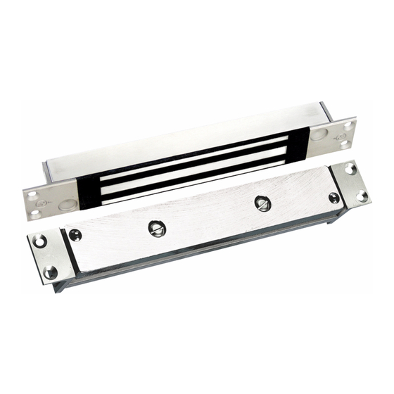
Figure 1 - SAM Series Magnalock
www.securitron.com
techsupport@securitron.com
1200 Lbs [544kg]
10.85" [275mm]
Height
1.5" [38mm]
Depth
1.19" [30mm]
12/24 Volts DC
Voltage: 30 VDC (Maximum)
Current: 1 Amp (Maximum)
Voltage: 30 VDC (Maximum)
Current: 125 mA (Maximum)
Along with these instructions and the
Magnalock
Page 1
ASSA ABLOY, the global leader
in door opening solutions
SAM
320mA
170mA
6.8mF
6.8mF
Hardware Pack
(See Section
PN# 500-10440
Rev. F, 02/12
Advertisement

Related Manuals for Assa Abloy Securitron SAM


Summary of Contents for Assa Abloy Securitron SAM
- Page 1 Securitron Magnalock Corp. www.securitron.com ASSA ABLOY, the global leader Tel 800.624.5625 techsupport@securitron.com in door opening solutions SHEAR ALIGNING MAGNALOCK MODEL SAM INSTALLATION AND OPERATING INSTRUCTIONS 1 INTRODUCTION Securitron’s Shear Aligning Magnalock “SAM” is intended for installations where concealed mounting in the door and frame is desired. The operating features allow self-alignment while securing the door when it closes.
-
Page 2: Recommended Tools
3.1 HARDWARE Phillips Flat Head Socket Flat Head Hex Wrench #10 X 3/4” Type “A” 10-32 X 3/8” 1/8” Thread Locking Compound Shim Plate Flush Mount Bracket Pack Floor Install Replacement Spring Pack (2 Springs) 4 RECOMMENDED TOOLS Router or Saber Saw 1/8”... - Page 3 The door and frame areas additionally need to be examined for mortising capabilities, sufficient size and should be free of any internal obstructions. The top-of-door installation is recommended as the most suitable location for protection from impact attacks. 5.2 Swinging Door The illustrations in Figure 2 demonstrate a SAM installed in a swinging door.
- Page 4 Locate and mark the desired lateral centerline position for the Magnalock/strike assembly on the face of the door. Using this door mark as reference, mark the same lateral center location of the Magnalock onto the door frame. Setting the depth center position of the Magnalock is more critical because there is not a lot of free depth in the door frame or door to accommodate any centering error.
- Page 5 It is recommended that the Magnalock face protrude approximately 1/16” [1.6mm] beyond the surface of the frame. Both Figures 4 and 5 show a shim plate between the lock mounting bracket and the flush mount bracket in order to raise the Magnalock above the frame surface.
- Page 6 The serrations on the brackets are .050” [1.3mm] apart which matches the screw thread pitch distance that mounts the strike. This feature will be explained during the final adjustment in Section 5.7. These end brackets may also be inverted to provide for deeper mounting configurations.
- Page 7 5.6.3 Hollow Aluminum Door (Deep Recess Top) For mounting of the strike assembly into doors with deep recessed surfaces as shown in Figure 9, no cutout for the strike assembly is required. Remove and invert the end brackets to increase the height range of the strike bracket assembly.
- Page 8 5.6.5 Soft Core Wood Door Use of the end brackets is recommended when installing the strike assembly on soft core wood style doors because a “pocketed” soft core door is not as strong in supporting the lateral forces applied to the strike assembly. Use of the end brackets will provide a much more sound and secure anchoring platform for the installation.
- Page 9 Slider Door Installation Figure 13 5.7 Strike Assembly Final Adjustments 5.7.1 Strike Level Adjustment (De-energized) De-energized adjustment of the strike height is important for proper door/lock operations. The example in Figure 14 illustrates the Magnalock with the proper adjustment. Without power applied to the Magnalock, both of the (conical) interference buttons should just clear the lock brackets.
-
Page 10: Electrical Installation
attracted to the Magnalock, but the strike and the interference buttons should pass completely into the locking position to secure the door. Test this operation several times to ensure consistent operation of the Magnalock/strike installation. WHEN THE MAGNALOCK IS ENERGIZED FOR A CONTINUOUS DUTY MODE, THE ADJUSTMENTS MADE MAKE IT A POSITIVE LOCKING MODE FOR CONTROLLED ACCESS. - Page 11 6.5 Electrical Wiring The following diagrams, Figures 17, 18, 19 and 20 represent the proper electrical wiring connections required for SAM Magnalock Standard, and for SAM BondSTAT “B”, DPS “D” and “BD” versions. SAM STANDARD ACCESS VERSION POWER CONTROL 2-WIRE MAGNALOCK SUPPLY DEVICE INPUT...
- Page 12 6.6 BondSTAT Sensor status wiring description The green and white wires supply electrical connection when the lock is ON and secure. The orange and white wires supply electrical connection when the lock is OFF or unsecure. 6.7 DPS – Door Position Sensor status wiring description ...
-
Page 13: Troubleshooting
8 MAGNALOCK MAINTENANCE 8.1 Visual Inspection Check the strike assembly for proper gap, suspension and free movement. Tighten strike adjustment screws as required. Check for build-up of debris on the Magnalock and strike armature. Clean as required. Check for rust on the Magnalock and strike assembly. - Page 14 Problem DPS Does Not Report Door Status Points of Reference Check strike mounting for proper alignment Table A / Section 5.6.6 Check for proper door closure Section 8.1 Solution Check for proper voltage/current on switch Section 2 Check resettable protection device Section 1 Problem The Magnalock Does Not Release...
- Page 15 1.2.2 Example B: (24VDC system) Devices Used 24VDC Amps SAM Magnalock 0.320 DK-11 Access 0.070 XDT-24 Delay 0.050 Total Current (0.440A) Rounded Up = 0.600A Using Table 2 (24VDC) Find: - Current Draw .600 Amps - Wire Distance 1000 Feet [305m] (One-Way) Solution: 14 Gauge is indicated for proper installation TO SOLVE: INTERSECT ROW (Total Current Draw) and INTERSECTING COLUMN (One- Way Wire Distance).
- Page 16 MAGNACARE LIFETIME REPLACEMENT WARRANTY www.securitron.com/en/site/securitron/About/MagnaCare-Warranty/ For warranty information visit PATENTS The Securitron Shear Aligning Magnalock is listed under U.S. patent #4,516,114 and 6,007,119. Additional patents pending PN# 500-10440 Page 16 Rev. F, 02/12...
Need help?
Do you have a question about the Securitron SAM and is the answer not in the manual?
Questions and answers