FANOX SIA-B User Manual
Self and dual powered
overcurrent & earth fault protection relay.
power t&d
Hide thumbs
Also See for SIA-B:
- Installation & commissioning manual (32 pages) ,
- User manual (114 pages)

Related Manuals for FANOX SIA-B


Summary of Contents for FANOX SIA-B
- Page 1 SIA B Self and Dual powered Overcurrent & Earth Fault Protection Relay USER´S MANUAL...
-
Page 2: Table Of Contents
5.2. States and Events ..........................28 5.3. Fault Reports ............................ 32 5.4. Date and Time by Real Time Clock (RTC) ..................32 5.5. Self-diagnosis ..........................32 5.6. Commands ............................33 5.7. Test Menu ............................33 5.8. Power supply ........................... 34 www.fanox.com SIAB_ENG_V1 2/81... - Page 3 8.2. Function codes ..........................68 8.3. Exemptions and error answers ...................... 69 8.4. Data type ............................69 8.5. Memory map of SIA-B ........................70 8.6. Commands Map ..........................74 8.7. Examples of ModBus frames ......................74 Writing the access password “5555” to equipment nº 1 ............ 74 8.7.1.
- Page 4 9.7. Front communications port ......................75 9.8. Commissioning ..........................76 10. APPENDIX ............................77 10.1. Identification ............................ 77 10.2. Checks .............................. 77 10.3. Test menu ............................77 10.4. Register of commissioning settings....................77 10.5. Comments ............................79 www.fanox.com SIAB_ENG_V1 4/81...
-
Page 5: Reception, Handling & Installation
It is necessary to inspect the equipment at the time it is delivered to ensure that the relays have not been damaged during transport. If any defect is found, the transport company and FANOX should be informed immediately. If the relays are not for immediate use, they should be returned to their original packaging. -
Page 6: Storage
All electrical power sources should be removed before performing this operation to avoid the risk of electrical discharge. This product must be disposed of in a safe way. It should not be incinerated or brought into contact with water sources like rivers, lakes, etc… www.fanox.com SIAB_ENG_V1 6/81... -
Page 7: Dimensions And Connection Diagrams
DIMENSIONS AND CONNECTION DIAGRAMS 2.1. Frontal view www.fanox.com SIAB_ENG_V1 7/81... -
Page 8: Case Dimensions
2.2. Case dimensions The dimensions are in mm. www.fanox.com SIAB_ENG_V1 8/81... -
Page 9: Connection Diagram
2.3. Connection diagram NOTE! STRIKER: 6 – 24 Vdc & < 0,1 Ws www.fanox.com SIAB_ENG_V1 9/81... -
Page 10: Terminals
Phase B current output for power supply Phase C current input for power supply Phase C current output for power supply Trip output +- Trip output - External trip C3-C4 Auxiliary power supply - Auxiliary power supply + www.fanox.com SIAB_ENG_V1 10/81... -
Page 11: Description
3.2. Equipment description The SIA-B equipment is a protection relay designed for secondary distribution. One of its main characteristics is the necessity of using specific current transformers for measurement and power supply. - Page 12 SICom communications program (supplied by FANOX). Besides, the frontal port can be used to power the equipment by using an USB cable which can be directly connected with PC.
-
Page 13: Functional Diagram
Auxiliary power: 24 Vdc Optional Battery power accessory: 5 V with Kitcom adaptor Monitoring and recording Events saved in the non-volatile FRAM* memory Commands Optional Real-Time Clock (RTC) Fault reports Test menu Self-diagnosis 3.3. Functional Diagram www.fanox.com SIAB_ENG_V1 13/81... -
Page 14: Model List
+ Trip Block for switch disconnector USB frontal 2 led’s + trip output (striker) + External trip input (49T) + 1 FLAG English, Spanish and German English, Spanish and Turkish English , Spanish and French English , Spanish and Russian www.fanox.com SIAB_ENG_V1 14/81... -
Page 15: Specific Cts
Specific CTs SIAB relay requires specific CTs to achieve the measurement and the power supply: Depending on the model we select, we have the following primary currents: The main characteristics of the transformers are: Technical specifications: www.fanox.com SIAB_ENG_V1 15/81... - Page 16 Ordering specifications: *** Different shape drawing on request Dimensions: www.fanox.com SIAB_ENG_V1 16/81...
-
Page 17: Protection Functions
Maximum Step Unit Default Phase inverse time overcurrent Permission Yes/No Curve (1*) Extremely Inverse Dial 0,05 1,25 0,01 1,25 0,10 7,00 0,01 1,00 Operating time 0,02 300,0 0,01 0,02 (1*) Inverse, Very inverse, Extremely inverse, Defined time www.fanox.com SIAB_ENG_V1 17/81... -
Page 18: Function. Neutral Instantaneous Overcurrent
The function activates at 100% of the pre-set input, and deactivates at 95%. The reset is instantaneous. The accuracy of the operation time is equal to the pre-set time plus a maximum of 30 ms. www.fanox.com SIAB_ENG_V1 18/81... -
Page 19: Function. Neutral Inverse Time Overcurrent
In order to deal with these situations, tripping is blocked when the phase current exceeds a pre-set value. Group Description Minimum Maximum Step Unit Default Trip blocking Blocking Yes/No Blocking limit 1,50 20,00 0,01 I nominal 7,00 www.fanox.com SIAB_ENG_V1 19/81... -
Page 20: Function. Thermal Image Protection
This protection function is adjusted by setting five different parameters: Function Description Minimum Maximum Pitch Unit Default Thermal image protection function Permission Yes/No 0,10 2,40 0,01 ζ heating ζ cooling ζ heating Alarm www.fanox.com SIAB_ENG_V1 20/81... - Page 21 Thermal image protection trip bit is active when the measurement of the thermal image is over 100% and it is reset when the measurement of the thermal image is under the adjusted alarm level. www.fanox.com SIAB_ENG_V1 21/81...
- Page 22 Thermal image measurement can be displayed on Measurement menu and Counters menu. Display is possible in Measurement menu. Display and thermal image value reset is possible in Counters menu. 4.6.4. Thermal protection curves This is the thermal curve for ζ = 3 minutes. www.fanox.com SIAB_ENG_V1 22/81...
-
Page 23: External Trip
There are available two protection setting groups. The setting group, which is activated in a particular moment, can be modified in the following way: Changing active group. In general settings menu there is an option to establish which group is active. www.fanox.com SIAB_ENG_V1 23/81... -
Page 24: Iec 60255-151 Curves
4.10. IEC 60255-151 Curves The SIA-B relay complies with the curves shown in standard IEC 60255-151 Curves: Inverse Curve Very Inverse Curve Extremely Inverse Curve There is a general mathematical equation that defines the time in seconds as a function of the current: ... - Page 25 SIAB_ENG_V1 25/81...
- Page 26 SIAB_ENG_V1 26/81...
- Page 27 SIAB_ENG_V1 27/81...
-
Page 28: Monitoring And Control
HMI, you have to go to the events menu and press and hold the "RESET" key until the number of events reads 1, and this event is registered as "Events deleted". To delete the events using communications, use the corresponding "delete events" command. To delete the events it is necessary to enter a password. www.fanox.com SIAB_ENG_V1 28/81... - Page 29 Factory settings - bit-11 EEPROM error - bit-12 EEPROM changed - bit-13 Events error - bit-00 Local communication - bit-01 HMI activity Local communication bit-16 Command select bit-23 Reset thermal image www.fanox.com SIAB_ENG_V1 29/81...
- Page 30 50P B Trip Phase B current bit-10 50P C Trip Phase C current - bit-11 50P Trip bit-04 51N Pick-up Neutral current bit-12 51N Trip Neutral current bit-04 50N Pick-up Neutral current bit-12 50N Trip Neutral current www.fanox.com SIAB_ENG_V1 30/81...
- Page 31 HMI activity: this state is active if any key has been pressed in the last 15 minutes. Local communication: this state becomes active if communications are detected in the front USB port. www.fanox.com SIAB_ENG_V1 31/81...
-
Page 32: Fault Reports
Problem in the protection block Eeprom error Problem in the eeprom memory, some group is corrupt. Remaining that setting (both group) are duplicated in Eeprom chip. Events error Error in the register of events in FRAM chip memory. www.fanox.com SIAB_ENG_V1 32/81... -
Page 33: Commands
5.7. Test Menu The SIA-B equipment has a test menu that can be used to check the operation of the signalling components (LED indicators) and the outputs. It is important to point out that the operation of the outputs is not guaranteed if the test is performed with the battery. -
Page 34: Power Supply
5.8. Power supply The SIA-B equipment is designed to be self-powered using the cell current. Besides, depending on model it is possible to select apart from self-powered, an auxiliary supply (230 Vac, 110 Vac or 24 Vdc). It can also be supplied from a USB cable which goes directly till PC. The USB is plugged into the front communications port. -
Page 35: Opening Mechanism: Striker
Striker activation The activation of the SIA-B trip output means that a capacitor has discharged on the output terminals. This discharge of energy is sufficient to activate a striker that mechanically acts on a mechanism to open the current circuit. The striker is connected directly to the SIA-B output, which supplies sufficient power to activate it (24 Vdc –... -
Page 36: Technical Specifications And Standards
0.02 to 300 s (step 0.01 s) Dial: 0.05 to 1.25 (step 0.01) Curve, activation level 110% Curve, deactivation level 100% Defined time, activation level 100% Defined time, deactivation level 95% Instantaneous deactivation Timing accuracy: 5% or 30 ms (greater of both) www.fanox.com SIAB_ENG_V1 36/81... - Page 37 Timing accuracy:± 5% regarding theoretical value 24 Vdc – 288 mJ (activation of the striker or low powered coil) Trip output Trip Blocking Switch disconnector using trip blocking Frequency 50/60Hz Current measure True RMS Sampling: 16 samples/cycle www.fanox.com SIAB_ENG_V1 37/81...
- Page 38 One phase self-power level: I > 0,8 x Is min Environment Operating temperature: -10 to 70ºC Storage temperature: -20 to 80 ºC Humidity: 95% Transformers Power supply and measurement specific CTs Mechanical features Metallic box Panel Mounting ¼ Rack-4U IP-54 panel mounted www.fanox.com SIAB_ENG_V1 38/81...
-
Page 39: Standards
0% IEC 61000-4-12 Interruptions: Damped RF oscillatory wave immunity Level 4: ±2kV Line-Line ±4kV Line-Ground IEC 61000-4-14 Voltage fluctuation immunity Class 3: 12% IEC 61000-4-17 Ripple on DC input power port immunity Level 4: 15% V DC www.fanox.com SIAB_ENG_V1 39/81... - Page 40 Emission standard for industrial environments EN 61000-6-2 General standard for immunity in industrial environments EN 55011 RF energy emissions Limitations for group class A EN 55022 IEC 60255-22-1 Interruptions: Damped RF oscillatory wave immunity Level 3 ISO 9001:2000 Quality Management System www.fanox.com SIAB_ENG_V1 40/81...
-
Page 41: Communication And Hmi
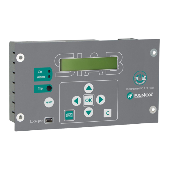
7.2. Indicators The SIA-B front panel has two LED pilot lights to show if the equipment is ON (LED ON) and if there has been an alarm (LED ALARM). The LEDs are switched off when the equipment is not On, or when there is not an alarm, and they are switched on when some of those situations occur. -
Page 42: Lcd And Keypad
7.3. LCD and keypad The front of the SIA-B relay is fitted with an alphanumeric LCD screen, measuring 20x2. This screen provides the user with access to read information about the settings parameters, measurements, state and events. All of this information is arranged in a system of menus. -
Page 43: Menus
▼ are used to increase or decrease the value. If an invalid value is entered during the process, the “C” key can be used to delete it. The navigation through the menus is described as graphically as possible below. www.fanox.com SIAB_ENG_V1 43/81... -
Page 44: Date-Time Menu
From the "sleep" mode screen, press the “◄” key to access the fault report. Using the “▲” and “▼” keys we find the fault report that we are looking for and pressing “OK” we can read the data of this fault report. www.fanox.com SIAB_ENG_V1 44/81... -
Page 45: Test Menu
“OK” to access the components that can be tested. TEST MENU y/n? ◄ ▼ ► without protection! OK hold Set Password -> 0 Set Password ◄▼▲► -> 5555 TEST MENU Led ON: not activated Led ON: <<ACTIVATED>> Led Alarm: ▲▼ not activated www.fanox.com SIAB_ENG_V1 45/81... - Page 46 Led Alarm: <<ACTIVATED>> Trip bistable: ▲▼ not activated Trip bistable: <<ACTIVATED>> Output 1: ▲▼ not activated Output 1: <<ACTIVATED>> www.fanox.com SIAB_ENG_V1 46/81...
-
Page 47: Functions Menu
7.5.8. Functions Menu The SIA-B relay menu is split up into 6 main parts: Measurements. State. Settings. Events. Counters Commands SIAB00001000AA MEASUREMENTS SIAB00001000AA 0.00 0.00 0.00 0.00 0.00 0.00 0.00 0.00 STATES ▲▼ SETTINGS GEN... -
Page 48: Measurements Menu
“MEASUREMENTS” screen and press “OK”. Use the “▲” and “▼” keys to position the cursor over the measurement and to see its value. ↑ MEASUREMENTS SIAB00001000AA 0.00 0.00 0.00 0.00 ↓ ↑ MEASUREMENTS 0.00 A ↓ 0.00 *A ▲▼ 0.00 A ▲▼ 0.00 A ▲▼ 0.00 A IMax ▲▼ 0.00 A ▲▼ www.fanox.com SIAB_ENG_V1 48/81... -
Page 49: States Menu
STATES SIAB00001000AA 0.00 0.00 0.00 0.00 ↓ ↑ STATES States GENERAL ↓ Trip: States GENERAL not activated External Trip: ▲▼ not activated Error Trip power: ▲▼ not activated 50 Hz: ▲▼ <<ACTIVATED>> Trip Block: ▲▼ not activated www.fanox.com SIAB_ENG_V1 49/81... - Page 50 Measurement Error: ▲▼ not activated Ready: ▲▼ <<ACTIVATED>> Settings changed ▲▼ Not activated Set Date/Time: ▲▼ not activated Local communication: ▲▼ not activated Factory Settings: ▲▼ not activated Error Eeprom: ▲▼ not activated Eeprom changed: ▲▼ not activated www.fanox.com SIAB_ENG_V1 50/81...
- Page 51 States Local COM: not activated MMI Activity: ▲▼ not activated Reset TI: not activated ↑ STATES States 50P ▲▼ ↓ Phase A Pickup: States 50P not activated Phase B Pickup: ▲▼ not activated Phase C Pickup: ▲▼ not activated www.fanox.com SIAB_ENG_V1 51/81...
- Page 52 Phase B Trip: ▲▼ not activated Phase C Trip: ▲▼ not activated Phase Trip: ▲▼ not activated ↑ STATES States 51P ▲▼ ↓ Phase A Pickup: States 51P not activated Phase B Pickup: ▲▼ not activated www.fanox.com SIAB_ENG_V1 52/81...
- Page 53 ▲▼ not activated Phase B Trip: ▲▼ not activated Phase C Trip: ▲▼ not activated Phase Trip: ▲▼ not activated States 50N ↑ STATES ▲▼ ↓ Ground Pickup: States 50N not activated Ground Trip: ▲▼ not activated www.fanox.com SIAB_ENG_V1 53/81...
- Page 54 ↑ STATES States 51N ▲▼ ↓ Ground Pickup: States 51N not activated Ground Trip: ▲▼ not activated ↑ STATES States INPUTS ▲▼ ↓ Input 1: States INPUTS not activated www.fanox.com SIAB_ENG_V1 54/81...
- Page 55 States OUTPUTS <<ACTIVATED>> Led Alarm: ▲▼ not activated Trip bistable not activated Output 1: ▲▼ not activated States TRIP BLOCKING ↑ STATES ▲▼ ↓ Phase A Blocking: States TRIP BLOCKING not activated Phase B Blocking: ▲▼ not activated www.fanox.com SIAB_ENG_V1 55/81...
- Page 56 Phase C Blocking: ▲▼ not activated Phase Blocking: ▲▼ not activated States 49 ↑ STATES ▲▼ ↓ Alarm: States 49 not activated Trip: ▲▼ not activated www.fanox.com SIAB_ENG_V1 56/81...
-
Page 57: Settings Menu
The method for navigating through the settings menu and the sequence to follow to change a setting are shown graphically below: SETTINGS GEN SIAB00001000AA ↑ 0.00 0.00 0.00 0.00 ↓ Select table SETTINGS GEN ↑ ↑ 1 = T.Activated ↓ ↓ Select table ↑ ▲▼ ↓ www.fanox.com SIAB_ENG_V1 57/81... - Page 58 Function Enable Settings 50P Set Password Function Enable -> 0 Set Password ◄▼▲► -> 5555 Function Enable NO -> NO Function Enable ▲▼ NO -> YES Function Enable NO > YES y/n SETTING CHANGED Function Enable Function Enable www.fanox.com SIAB_ENG_V1 58/81...
- Page 59 1.00 xIn Operating Time ▲▼ 0.02 s GEN Sett(1) 51P ↑ SETTINGS ▲▼ ↓ Function Enable Settings 51P Curve type ▲▼ Def Tim Time Dial ▲▼ 0.05 Current Tap ▲▼ 0.20 xIn Sett(1) 50N ▲▼ Function Enable www.fanox.com SIAB_ENG_V1 59/81...
- Page 60 Time Delay ▲▼ 0.02 s Sett(1) 51N ▲▼ ▲▼ Function Enable Curve type ▲▼ E.I. Time Dial ▲▼ 1.25 Current Tap ▲▼ 0.50 xIn(1.00) Time Delay ▲▼ 0.02 s GEN Settings TRIP BLOCKING ↑ SETTINGS ▲▼ ↓ www.fanox.com SIAB_ENG_V1 60/81...
- Page 61 Settings TRIP BLOCKING Set Password Function Enable -> 0 Set Password ◄▼▲► -> 5555 Function Enable NO -> NO Function Enable ▲▼ NO -> YES Function Enable NO > YES y/n SETTING CHANGED Function Enable Function Enable www.fanox.com SIAB_ENG_V1 61/81...
- Page 62 Current Tap ▲▼ 0.20 xIn Heating Constant ▲▼ 3 min Cooling constant ▲▼ 3x heating constant Alarm ▲▼ To access the general settings from the “SETTINGS” menus, press “◄” GEN Identification ↑ SETTINGS ◄ free text ↓ www.fanox.com SIAB_ENG_V1 62/81...
- Page 63 Frequency ▲▼ 50Hz Serial Number ▲▼ Language ▲▼ ENG. Active Settings Group ▲▼ Nominal current ▲▼ CT type ▲▼ CT008 Local COM Address ▲▼ Password ▲▼ **** www.fanox.com SIAB_ENG_V1 63/81...
-
Page 64: Events Menu
4/5: 0 ▲▼ ┐ 52 Open Error ┐ 52 Open Error Set Password EVENTS ↑ RESET -> 0 There are 5 ↓ Set Password ◄▼▲► -> 5555 Confirm Erased Events y/n? EVENTS ↑ There are 1 ↓ www.fanox.com SIAB_ENG_V1 64/81... - Page 65 Position of the event within the list of events Events generated by a state activation or reset Associated measurement (if it has one) Time Associated measurement Date 01/01/00 00:54:18600 1/99 measurement Events erased Events erased Activated or Not activated Event description www.fanox.com SIAB_ENG_V1 65/81...
-
Page 66: Commands Menu
Press the "OK" key to perform a command, and press the "OK" key again to confirm the command. COMMANDS SIAB00001000AA ↑ 0.00 0.00 0.00 0.00 ↓ EXECUTE COMMAND y/n COMMANDS ↑ Reset TI ↓ CONFIRM COMMAND y/n EXECUTE COMMAND y/n Reset TI Reset TI COMMANDS ↑ ↓ www.fanox.com SIAB_ENG_V1 66/81... -
Page 67: Modbus Rtu Protocol
MODBUS RTU PROTOCOL This document describes the steps to follow to read and write data on the SIA-B relay, as per the ModBus/RTU protocol. This memory map is only valid for one piece of equipment and one version of the memory. The positions of existing objects in the memory remain fixed from one version to the next, but new objects will naturally have new addresses which will, in turn, remain fixed in future versions. -
Page 68: Modbus Packaged Format
Multiple represent one or more settings. The registers are values of Registers 2 bytes of length, transmitted with the most important byte at first. The maximum number of register to be written in a package is 60. www.fanox.com SIAB_ENG_V1 68/81... -
Page 69: Exemptions And Error Answers
Number in floating decimal point “Float” of 4 bytes FLOAT String: Length variable character chain. Final of String marked with ‘\0’. ASCIIxx xx/2 E. g.: “ABC” 0x41x42x43x00..Year(UINT).month(UCHAR).day(UCHAR).hour(UCHAR).minutes(UCHAR).seconds(UCHAR).hu ndredth(UCHAR).thousandth(UINT) EVENT2 Criteria Directory(UINT).Event Identifier(UINT).Value(UINT).Associated Measure(float).Date and Time(FH) EVENTO2 Antiquity(UINT).Event(EVENT2) www.fanox.com SIAB_ENG_V1 69/81... -
Page 70: Memory Map Of Sia-B
DENUM NOYES DENUMBAUD 4800 bauds 9600 bauds 19200 bauds 38400 bauds DENUM LANGUAGE English Spanish Depending on model 8.5. Memory map of SIA-B Start Number of Function Description Format address registries Write the Directory of UINT Event Write the number of the... - Page 71 03 y 16 LANGUAGE 03 y 16 Setting LONG Active group 03 y 16 Setting FLOAT Nominal current 03 y 16 Setting FLOAT CT type 03 y 16 Setting LONG Local address 03 y 16 Setting ASCII4 Password[4] www.fanox.com SIAB_ENG_V1 71/81...
- Page 72 03 y 16 Setting FLOAT Blocking trip tap Confirm setting Equipment identifier Confirm setting Frequency Confirm setting Serial number Confirm setting Language Confirm setting Active group Confirm setting Nominal current Confirm setting CT type Confirm setting Local address www.fanox.com SIAB_ENG_V1 72/81...
- Page 73 Confirm setting F51N Definite time Confirm setting F49 Permission Confirm setting F49 Tap Confirm setting F49 Heating constant Confirm setting F49 cooling constant Confirm setting F49 Alarm Confirm setting Blocking trip permission Confirm setting Blocking trip tap www.fanox.com SIAB_ENG_V1 73/81...
-
Page 74: Commands Map
Number of L registers Number of bytes Password 35,35,35,35 Checksum H Checksum L And SIA respond OK: Address Function H start address L start address Number of H registers Number of L registers Number of bytes Checksum H Checksum L www.fanox.com SIAB_ENG_V1 74/81... -
Page 75: Commissioning
9.7. Front communications port To perform this test, connect a PC with the SICom software program to the SIA-B relay, and check that there are no communication errors. It is important to check communications port (COM) which is assign to USB. -
Page 76: Commissioning
It is recommended that the following safety measures are taken before starting up the facility for the first time, or after a trip event: FANOX recommends the use of the KITCOM accessory with a battery in the front port. This additional energy source allows the relay to be monitored and the trip to function without the need for self-power in any breakdown situation. -
Page 77: Appendix
On LED: Output 1 Alarm LED: Trip indicator: 10.4. Register of commissioning settings Password: …………………………………………………………………………… Identification: ………………………………………………………………………… CT type: ……………………..…………………………………………………………….. Nominal current: ……………………..…………………………………………………… Enabled Disabled Permission Tap......…………… x In Operating Time: ..………... www.fanox.com SIAB_ENG_V1 77/81... - Page 78 Extrem. Inverse Definite time Dial……....………… Operating Time…..…..…… Enabled Disabled Permission Tap……..………………………… x In ζ heating: …………………………. min ζ cooling: …………………………. ζ heating Alarm: …………………………. Trip blocking Enabled Disabled Permission Blocking level.....………… x In www.fanox.com SIAB_ENG_V1 78/81...
-
Page 79: Comments
10.5. Comments …………….....……………………………………………………………………………..… …………….....……………………………………………………………………………..… ……………....……………………………………………………………………………..…. …………….....……………………………………………………………………………..… …………….....……………………………………………………………………………..… …………….....……………………………………………………………………………..… …………….....……………………………………………………………………………..… …………….....……………………………………………………………………………..… …………….....……………………………………………………………………………..… …………….....……………………………………………………………………………..… …………….....……………………………………………………………………………..… …………….....……………………………………………………………………………..… …………….....……………………………………………………………………………..… …………….....……………………………………………………………………………..… …………….....……………………………………………………………………………..… …………….....……………………………………………………………………………..… …………….....……………………………………………………………………………..… …………….....……………………………………………………………………………..… …………….....……………………………………………………………………………..… …………….....……………………………………………………………………………..… …………….....……………………………………………………………………………..… …………….....……………………………………………………………………………..… …………….....……………………………………………………………………………..… …………….....……………………………………………………………………………..… Person in charge of commissioning………..……..…………..Date……….....… Maintenance performed on the………………….. by ………..………………………………….. www.fanox.com SIAB_ENG_V1 79/81... - Page 80 NOTES: ……………………………………………………………………………………………………..… ……………………………………………………………………………………………………..… ……………………………………………………………………………………………………..… ……………………………………………………………………………………………………..… ……………………………………………………………………………………………………..… ……………………………………………………………………………………………………..… ……………………………………………………………………………………………………..… ……………………………………………………………………………………………………..… ……………………………………………………………………………………………………..… ……………………………………………………………………………………………………..… ……………………………………………………………………………………………………..… ……………………………………………………………………………………………………..… ……………………………………………………………………………………………………..… ……………………………………………………………………………………………………..… ……………………………………………………………………………………………………..… ……………………………………………………………………………………………………..… ……………………………………………………………………………………………………..… ……………………………………………………………………………………………………..… ……………………………………………………………………………………………………..… ……………………………………………………………………………………………………..… ……………………………………………………………………………………………………..… ……………………………………………………………………………………………………..… ……………………………………………………………………………………………………..… ……………………………………………………………………………………………………..… ……………………………………………………………………………………………………..… ……………………………………………………………………………………………………..… www.fanox.com SIAB_ENG_V1 80/81...
- Page 81 FANOX ELECTRONIC S.L. Parque Tecnológico de Bizkaia Astondo bidea, Edif. 604 ES-48160 DERIO BIZKAIA Tel. + 34 94 471 14 09 Fax + 34 94 471 05 92 fanox@fanox.com www.fanox.com www.fanox.com 81/81...
Need help?
Do you have a question about the SIA-B and is the answer not in the manual?
Questions and answers