
Subscribe to Our Youtube Channel
Related Manuals for Clarke Contractor CFIS 250


Summary of Contents for Clarke Contractor CFIS 250
- Page 1 0908 10” FLIPOVER SAW 10” FLIPOVER SAW (Combined Table and Compound Mitre Saw) Model CFIS 250 Operating & Maintenance Instructions...
-
Page 2: Declaration Of Conformity
When disposing of this product, do not dispose of with general waste. It must be disposed of according to the laws governing Waste Electrical and Electronic equipment, at a recognised disposal facility. -
Page 3: Table Of Contents
Thank you for purchasing your new CLARKE 10” FLIPOVER SAW. Before attempting to operate this machine, please read this instruction manual thoroughly and follow all directions carefully. In doing so you will ensure the safety of both yourself and others around you, and, at the same time, you should look forward to it providing long and trouble free service. -
Page 4: Specifications
SPECIFICATIONS Model No ................CFIS 250 Part No.................. 6500690 Motor ..................230V~ 50Hz 1ph Input Power Rating ............2.0Kw Speed ................3000 RPM Input Current ..............9Amps Fuse rating ..............13Amps Duty Cycle ................S6 40%** Saw Blade ................250mm (10”) dia. 30mm Bore TCT Saw Blade Maximum Speed Rating ........ -
Page 5: Safety Precautions
SAFETY PRECAUTIONS KEEP WORK AREA CLEAN : Cluttered areas and benches invite injuries. CONSIDER WORK AREA ENVIRONMENT: Do not expose power tools to rain. Do not use power tools in damp, or wet locations. Keep the work area well lit. Do not use this saw in the presence of flammable liquids or gases. GUARD AGAINST ELECTRIC SHOCK: Avoid body contact with earthed, or grounded surfaces, e.g. - Page 6 WARNING: The use of any accessory, or attachment, other than those recommended in this manual, may present a risk of personal injury. HAVE YOUR TOOL REPAIRED BY A QUALIFIED PERSON: This electric tool is in accordance with the relevant safety requirements. Repairs should only be carried out by qualified persons using original spare parts, otherwise this may result in considerable danger to the user.
-
Page 7: Additional Safety Rules For Table Saws
MAXIMUM BLADE EXTENSION: Have the blade extended to approximately 2-4mm above the top of the workpiece. Additional blade exposure could be potentially dangerous. DO NOT REACH OVER: Do not reach over, or behind the blade for any reason. SMALL PIECES AND TRAPPED PIECES: Do not pick up small pieces of cut-off material from the table. Remove them by pushing them off the table with the push stick. -
Page 8: Electrical Connections
ELECTRICAL CONNECTIONS WARNING! THIS APPLIANCE MUST BE EARTHED. Connect the mains lead to a 230 volt (50Hz) domestic electrical supply via a standard 13 amp BS 1363 plug fitted with a 13 amp fuse, or a suitably fused isolator switch. IMPORTANT: The wires in the mains lead are coloured in accordance with the following code: Green &... -
Page 9: Features
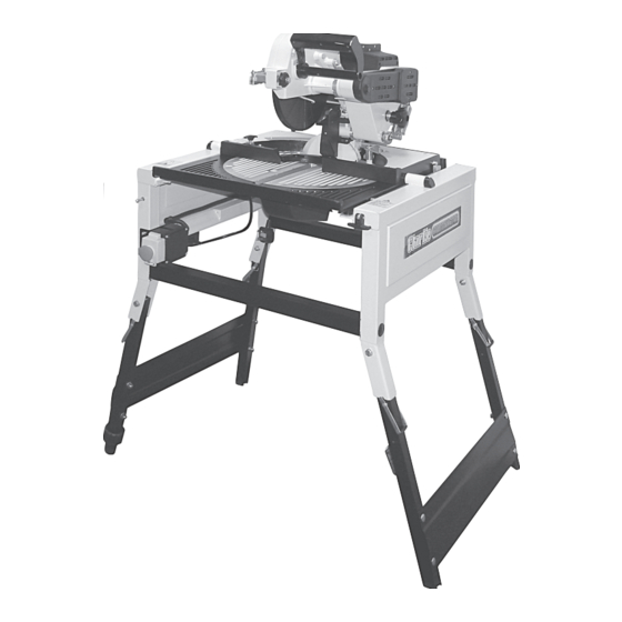
FEATURES • The machine may be used in either the Mitre Saw mode, or Table Saw mode, as shown below. • The table saw is used for rip cutting, cross cutting, including cross cut mitres, and bevel ripping. See Specifications on page 4 for limitations of use. •... -
Page 10: Glossary Of Terms
GLOSSARY OF TERMS Arbor The shaft on which a cutting tool is mounted. Crosscut A cutting operation made across the width of the workpiece - across the grain. Featherboard A device which can help guide workpieces during rip type operation. Heel Misalignment of the blade. -
Page 11: Unpacking And Checking Contents
Blade Guard complete Set of Hex. Wrenches M. Double open ended Spanner Should any component be missing or damaged in transit, please contact your CLARKE dealer immediately, or CLARKE Customer Service Department on 020 8558 7400 WARNING! DO NOT plug the table saw into the mains until it is fully assembled and checks made... -
Page 12: Familiarisation & Preparation For Use
FAMILIARISATION AND PREPARATION FOR USE Your Flipover saw is fully assembled at the factory, Once unpacked, very carefully, and with assistance, either invert the unit so that it rests on the table top as shown in Fig.1, or rest it on its rear edge. - Page 13 Fig.3 • Manoeuvre the riving knife so that it is positioned as shown in Fig.3, then, holding the assembly to maintain its position, screw in and tighten the locking knob - firmly. REAR IMPORTANT To prevent damage to the blade guard link mechanism when raising the saw blade it is important that the operating handle is disengaged.
- Page 14 NOTE: It is ESSENTIAL that either the Rip Fence, or the Mitre Gauge is used for all Table Saw operations, as described under ‘Cutting Methods’ on pages 19-22 in this manual. These components must be assembled as follows: The Rip Fence The rip fence should be used for all ripping operations.
- Page 15 The Mitre Gauge Fig.9 The Mitre Gauge should be used for all cross cutting operations. Attach the sliding bar to the underside of the mitre gauge, securing with the large hand knob, then, attach the mitre gauge to the mitre gauge fence using the two knobs shown in Fig.9.
-
Page 16: Preparing The Mitre Saw
Changing From Table Saw to Mitre Saw Mode NOTE: THE TABLE MAY ONLY BE TURNED FROM TABLE SAW MODE, WHEN THE SAW BLADE IS IN THE RAISED POSITION. When changing from table saw to Mitre Saw mode: Ensure the blade is in the fully raised position. - Page 17 B. Preparing The Mitre Saw 1. Remove Blade Guard • With the saw in table saw mode, it is first of all necessary to remove the blade guard by undoing and removing the pivot bolt. Replace the bolt with nut and flat washer in the removed blade guard for safe keeping.
- Page 18 4. Park Riving Knife Fig.16 • With the blade in the fully raised position, undo the riving knife locking knob and manoeuvre the riving knife so that it is in its ‘parked’ position, alongside the blade guard as shown in Fig.16. Please note, that subsequently, whenever it is desired to rotate the table to table saw mode, the riving knife may be positioned accordingly at this stage.
-
Page 19: Operation
OPERATION A. The Table Saw The table saw is used for all ripping and bevel ripping operations. It may also be used for cross cutting, including cross cut mitres, on pieces wider than can be accommodated using the Mitre saw, but thickness is limited - see the Note below. -
Page 20: Cutting Methods
NOTE: The table saw may be used to cut pieces up to 65mm thick with the blade at 90 degrees and up to 36mm thick with the blade set at 45 degrees. Fig.22 • Ensure the riving knife is correctly positioned. •... - Page 21 Fig.25 NEVER exert pressure with the hand guiding the piece being cut off.. • If the width of rip is narrower than 50mm (2”), the push stick cannot be used because it will inter fere with the guard. It is therefore necessary to use an auxiliary fence and push block as shown in Fig.25.
- Page 22 B. Crosscutting Crosscutting is the term used to describe cuts Fig.30 Cross cutting, with support made in timber across the grain. This type of cut requires the use of the MITRE GAUGE. This includes bevel cutting, mitre cutting and compound mitre cutting (described later in this paragraph).
- Page 23 F. Compound Mitre Cutting Compound mitre cutting is a combination of mitre cutting and bevel crosscutting. The cut is made at an angle other than 90 to both the edge and the flat side of the wood. • Adjust the mitre gauge and the blade to the desired angle. •...
-
Page 24: The Mitre Saw
B. The Mitre Saw Fig.34 With the table in mitre saw mode, all cross cutting operations may be made. These include straight cuts - at 90 degrees to the grain, mitre cuts, as the name suggests, bevel cuts and compound mitre/bevel cuts. - Page 25 2. Mitre cutting Fig.36 This is a cross cutting operation, except that the saw blade is set at an angle to the work, but remains perpendicular to the table. The head is mounted on the table which is free to rotate by up to 45 , to the left and right.
-
Page 26: Maintenance
Changing the Blade • Use only Clarke Blades - Damage caused by the use of blades other than those supplied by Clarke International will invalidate the guarantee (see parts list for part numbers). • Replace the blade when teeth become damaged or dull. -
Page 27: Changing The Drive Belt
Changing the Drive Belt Should the saw blade tend to bind in the workpiece, this is an indication that the drive belt needs either replacing, or adjusting. To check, proceed as follows: Remove the plastic belt cover - ref: Fig 42, (5 securing screws). - Page 28 Ensuring Head is Square Fig.46 It is important to ensure the saw blade is square to the Back Fence at all times to ensure absolute accuracy when both cross cutting and ripping, using the table saw. Check periodically by grasping the head lowering handle and turning to retract the blade guard, thereby exposing the saw blade.
-
Page 29: Riving Knife Adjustments
Riving Knife Adjustment Fig.49 Should the Riving Knife require adjusting. proceed as follows: In Mitre Saw mode, allow the head to rise to its fullest extent. Undo the locking knob - C Hold bolt head - B and slacken locknut A. DO NOT do this in reverse. -
Page 30: Trouble Shooting
TROUBLE SHOOTING TROUBLE PROBABLE CAUSE REMEDY Saw will not start 1. Saw not plugged in 1. Plug in the machine 2. Fuse blown or circuit breaker 2. Replace fuse or reset circuit tripped breaker 3. Power cable damaged 3. Have cable replaced by authorised service centre Material Pinches 1. -
Page 31: Parts Lists And Diagrams
PARTS DIAGRAMS... - Page 34 PARTS LISTS No. Description Part No No. Description Part No Screw NJFIS250001 Bush NJFIS250059 Fan Cover NJFIS250002 Gear Wheel NJFIS250060 Motor Shell NJFIS250003 Locking Handle NJFIS250061 M8 Hex Nut NJFIS250004 Spring NJFIS250062 Frame NJFIS250005 Spring Cover NJFIS250063 450V 20µf Capacitor NJFIS250006 Handle Cover NJFIS250064...
- Page 35 No. Description Part No No. Description Part No Knob NJFIS250117 Guide For Knife NJFIS250176 M6x8 Screw NJFIS250118 Knob NJFIS250177 Pointer NJFIS250119 M8x100 Pin Bolt NJFIS250178 Knob NJFIS250120 Wire NJFIS250179 Quadrant NJFIS250121 480 Hex Wrench NJFIS250180 Guide NJFIS250122 M5x52 Bolt NJFIS250181 M6x23 Screw NJFIS250123 400V Switch...
Need help?
Do you have a question about the Contractor CFIS 250 and is the answer not in the manual?
Questions and answers