
Related Manuals for Clarke CCO14C


Summary of Contents for Clarke CCO14C
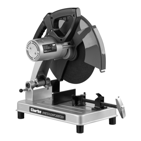
- Page 1 ABRASIVE CUT-OFF SAW MODEL NO: CCO14C PART NO: 6470161 OPERATION & MAINTENANCE INSTRUCTIONS ORIGINAL INSTRUCTIONS LS0618 - ISS 2...
-
Page 2: Environmental Recycling Policy
INTRODUCTION Thank you for purchasing this CLARKE Abrasive Cut-Off Saw which is suitable for cutting any ferrous metals which are compatible with the type of abrasive wheel fitted. Before attempting to use this product, please read this manual thoroughly and follow the instructions carefully. -
Page 3: General Power Tool Safety Warnings
GENERAL POWER TOOL SAFETY WARNINGS WARNING: READ ALL INSTRUCTIONS. FAILURE TO FOLLOW ALL INSTRUCTIONS LISTED BELOW MAY RESULT IN ELECTRIC SHOCK, FIRE AND/ OR SERIOUS INJURY. THE TERM “POWER TOOL” IN THE WARNINGS REFERS TO YOUR SAW. Save all warnings and instructions for future reference. 1) WORK AREA SAFETY a. -
Page 4: Personal Safety
3) PERSONAL SAFETY a. Stay alert, watch what you are doing and use common sense when operating a power tool. Do not use a power tool while you are tired or under the influence of drugs, alcohol or medication. A moment of inattention while operating power tools may result in serious personal injury. -
Page 5: Additional Warnings For Cut-Off Saws
12. Ensure you use the correct type of abrasive disc for the type of material being cut. Metal cutting & masonry abrasive discs are available from your Clarke dealer. NEVER cut magnesium, wood, or non-ferrous metals. Parts & Service: 020 8988 7400 / E-mail: Parts@clarkeinternational.com or Service@clarkeinternational.com... -
Page 6: Electrical Connections
ELECTRICAL CONNECTIONS WARNING: READ THESE ELECTRICAL SAFETY INSTRUCTIONS THOROUGHLY BEFORE CONNECTING THE PRODUCT TO THE MAINS SUPPLY. This product is provided with a standard 13 amp, 230 volt (50Hz), BS 1363 plug, for connection to a standard, domestic electrical supply. Should the plug need changing at any time, ensure that a plug of identical specification is used. -
Page 7: Unpacking And Assembly
UNPACKING AND ASSEMBLY Unpack the saw carefully and ensure that the following items are in the box. In the event of any deficiencies you should contact your Clarke dealer immediately. • Abrasive Cut-off Saw • 355mm Cutting disc (supplied fitted) •... -
Page 8: Vice Operation
OPERATION VICE OPERATION 1. Turn the handle counterclockwise to remove clamping pressure. 2. Lift the vice lever up. 3. Pull handle out as far as desired. • vice may be pushed forward into the work without turning the handle. 4. Lower the vice lever then tighten the vice on to the work using the handle. TRIGGER SWITCH 1. -
Page 9: To Change The Cutting Angle
ADJUSTMENTS WARNING: TURN OFF AND UNPLUG THE SAW BEFORE MAKING ANY ADJUSTMENTS. MAKE SURE THE TRIGGER SWITCH IS IN THE OFF POSITION. TO CHANGE THE CUTTING ANGLE 1. Use the hex wrench provided to loosen (do not remove) the two fence bolts. -
Page 10: To Change The Spacing Between The Fence And Vice
ADJUSTMENTS OR REMOVING OR INSTALLING CUTTING WHEELS. BE SURE THE TRIGGER SWITCH IS IN THE OFF POSITION. Cutting discs are available from your Clarke dealer - Part Number: 6470800 1. With the motor arm in the ‘UP’ position, rotate the blade guard out of the way as shown. -
Page 11: Depth Stop
DEPTH STOP The depth stop is set at the factory for a new 14" (355mm) cutting disc. This can be adjusted as the wheel wears. 1. Loosen the jam nut. 2. Loosen the depth stop bolt. 3. Adjust the bolt to desired height. 4. -
Page 12: Changing The Carbon Brushes
CHANGING THE CARBON BRUSHES These will naturally wear with use and require replacing. They should be checked periodically as follows: 1. Unscrew and remove the plastic caps on the end of the motor with a screwdriver. 2. Pull out the brushes complete with springs and retainers. -
Page 13: Parts Diagram
PARTS DIAGRAM Parts & Service: 020 8988 7400 / E-mail: Parts@clarkeinternational.com or Service@clarkeinternational.com... -
Page 14: Parts List
PARTS LIST Description Description Description Bolt M6x12 Side Cover Assembly Screw M5x10 Spark Deflector Nut M8 Rear Cover Lock Nut M6 Bolt M10x20 Screw M5x10 + Washer Base Assembly Flange Washer Screw M4x10 Bolt M8x12 + Washer Outer Flange Spring Washer 4 Rubber Foot Cutting disc Locking Washer 4... -
Page 15: Declaration Of Conformity
DECLARATION OF CONFORMITY Parts & Service: 020 8988 7400 / E-mail: Parts@clarkeinternational.com or Service@clarkeinternational.com...
Need help?
Do you have a question about the CCO14C and is the answer not in the manual?
Questions and answers