Advertisement
Access & Power Integration
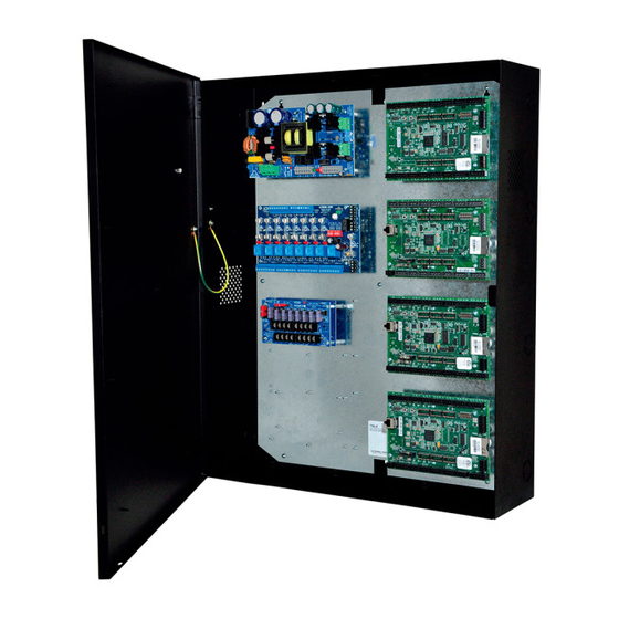
Trove2SL2
- Trove2 enclosure with
Altronix/Sielox backplane (TSL2)
Installation Guide
Trove2SL2 accommodates various combinations of Sielox boards with or without Altronix power supplies and accessories for
access control systems.
1. Remove backplane from enclosure prior to mounting (do not discard hardware).
2. Mark and predrill holes in the wall to line up with the top keyholes in the enclosure. Install the upper fasteners and
screws in the wall with the screw heads protruding. Place the enclosure's upper keyholes over the screws, level and
secure. Mark the position of the lower holes. Remove the enclosure. Drill the lower holes and install the fasteners.
Place the enclosure's upper keyholes over the upper screws. Install the lower screws and make sure to tighten all screws
(Enclosure Dimensions, pg. 4).
3. Mount included UL Listed tamper switch (Altronix Model TS112 or equivalent) in desired location, opposite hinge.
Slide the tamper switch bracket onto the edge of the enclosure approximately 2" from the right side (Fig. 1, pg. 1).
Connect tamper switch wiring to the Access Control Panel input or the appropriate UL Listed reporting device.
To activate alarm signal open the door of the enclosure.
4. Mount Altronix/Sielox boards to backplane, refer to pages 2-3.
Hardware:
Nylon or Metal Standoff
5/16" Pan Head Screw
All registered trademarks are property of their respective owners.
Overview:
Installation Instructions for Trove2:
TSL2
- Altronix/Sielox backplane only
TSL2_Rev. 110217
Tamper
Switch
(provided)
Enclosure
Enclosure
to Access Control
Panel or
UL Listed
Reporting
Device
Fig. 1
Edge of
Advertisement
Table of Contents

Subscribe to Our Youtube Channel
Related Manuals for Altronix TSL2


Summary of Contents for Altronix TSL2
- Page 1 (Enclosure Dimensions, pg. 4). 3. Mount included UL Listed tamper switch (Altronix Model TS112 or equivalent) in desired location, opposite hinge. Slide the tamper switch bracket onto the edge of the enclosure approximately 2” from the right side (Fig. 1, pg. 1).
- Page 2 Sub-Assembly Boards and Sielox AC-1700 Modules 1. Fasten standoffs (provided) to pems that match the hole pattern for Altronix Power Supply/Chargers or Altronix Sub-Assembly boards (Fig. 2, pg. 2). Fasten metal standoffs in the correct locations to provide proper grounding, see below (Fig.
- Page 3 TSL2 Dimensions 25.375” x 19.375” x 0.325” (644.5mm x 482.6mm x 8.3mm) 19.375” (482.6mm) 7.5” 7.5” (190.5mm) (190.5mm) 0.156” ( 3.96mm) 25.375” (644.5mm) 12.62” (320.6mm) 1.0” (25.4mm) 0.45” 1.0” (11.4mm) (25.4mm) 7.5” 7.5” (190.5mm) (190.5mm) 9.2” (233.7mm) Trove2SL2 - 3 -...
- Page 4 (133.35mm) (50.8mm) Altronix is not responsible for any typographical errors. 140 58th Street, Brooklyn, New York 11220 USA | phone: 718-567-8181 | fax: 718-567-9056 web site: www.altronix.com | e-mail: info@altronix.com | Made in U.S.A. MEMBER IITrove2SL2 A16S - 4 -...
Need help?
Do you have a question about the TSL2 and is the answer not in the manual?
Questions and answers