Molecular Devices ImageXpress Pico Installation Manual
Automated cell imaging system with cellreporterxpress software version 2.1
Hide thumbs
Also See for ImageXpress Pico:
- Installation manual (88 pages) ,
- Calibration kit manual (33 pages) ,
- Installation manual (58 pages)

Subscribe to Our Youtube Channel
Related Manuals for Molecular Devices ImageXpress Pico


Summary of Contents for Molecular Devices ImageXpress Pico
- Page 1 ImageXpress™ Pico Automated Cell Imaging System with CellReporterXpress™ Software Version 2.1 Installation Guide 5063666 F May 2019...
- Page 2 For research use only. Not for use in diagnostic procedures. The trademarks mentioned herein are the property of Molecular Devices, LLC or their respective owners. These trademarks may not be used in any type of promotion or advertising without the prior written permission of Molecular Devices, LLC.
-
Page 3: Table Of Contents
Contents Safety Information Warnings, Cautions, Notes, and Tips Symbols on Instrument Labels Protective Housing Electrical Safety Moving Parts Safety Lifting Hazard Chemical and Biological Safety Chapter 1: ImageXpress Pico Automated Cell Imaging System ImageXpress Pico System Features CellReporterXpress Software Features Theory of Operation Obtaining Support Product Documentation About This Guide... - Page 4 ImageXpress Pico Personal Imaging System Installation Guide Inserting the Plate Holder or Slide Holder Chapter 5: Environmental Control System Environmental Control System Warnings and Cautions Environmental Control System Hardware Using the Environmental Control System Appendix A: Instrument Specifications Instrument Dimensions without Environmental Control...
-
Page 5: Safety Information
When warnings and cautions are displayed in this guide, be careful to follow the specific safety information related to them. The following user-attention statements can be displayed in the text of Molecular Devices user documentation. Each statement implies a particular amount of observation or... -
Page 6: Symbols On Instrument Labels
ImageXpress Pico Personal Imaging System Installation Guide Symbols on Instrument Labels Each safety label found on the instrument contains an alert symbol that indicates the type of potential safety hazard related to the label. The following table lists the alert symbols that can be found on Molecular Devices instruments. -
Page 7: Protective Housing
For products under the requirement of the WEEE directive, contact your dealer or local Molecular Devices office for the procedures to facilitate the proper collection, treatment, recovery, recycling, and safe disposal of the device. Indicates the environmental friendly use period for China RoHS. The symbol may indicate the number of years in the use period. -
Page 8: Electrical Safety
Electrical Safety To prevent electrically related injuries and property damage, inspect all electrical equipment before use and immediately report all electrical deficiencies. Contact Molecular Devices Technical Support to service equipment that requires the removal of covers or panels. WARNING! HIGH VOLTAGE. - Page 9 7. Connect the power cord into the power port. 8. Press the Power button to power on the instrument. Note: If the instrument still does not power on after you change the fuses, contact Molecular Devices Technical Support. See Obtaining Support on page 21 for details.
-
Page 10: Moving Parts Safety
ImageXpress Pico Personal Imaging System Installation Guide Moving Parts Safety The instrument contains moving parts that can cause injury. Under normal conditions, the instrument is designed to protect you from these moving parts. To prevent injury: Never try to exchange labware, reagents, or tools while the instrument is operating. -
Page 11: Chemical And Biological Safety
Safety Information Chemical and Biological Safety Normal operation of the instrument can involve the use of materials that are toxic, flammable, or otherwise biologically harmful. When using such materials, observe the following precautions: Handle infectious samples based on good laboratory procedures and methods to prevent the spread of disease. - Page 12 ImageXpress Pico Personal Imaging System Installation Guide 5063666 F...
-
Page 13: Chapter 1: Imagexpress Pico Automated Cell Imaging System
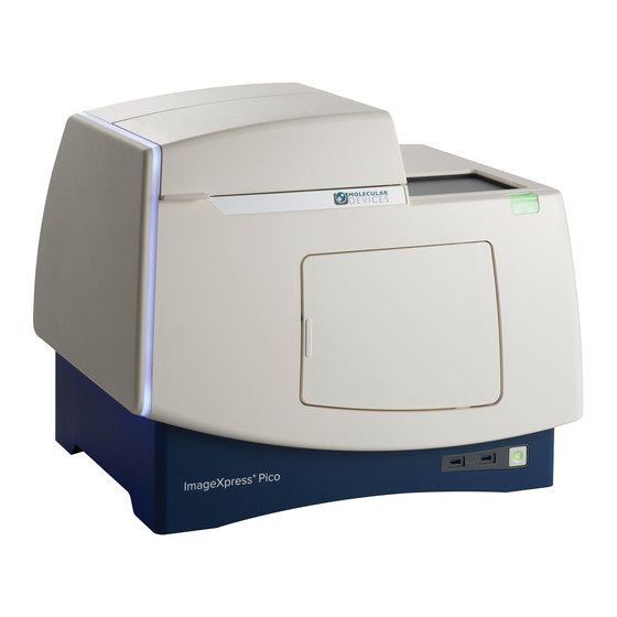
Chapter 1: ImageXpress Pico Automated Cell Imaging System The Molecular Devices® ImageXpress™ Pico Automated Cell Imaging System is an affordable all-in-one platform for automatically acquiring and analyzing images from fluorescently labeled biological samples in plates and slides. It enables you to increase the throughput of your image acquisition and analysis, allowing you to gain insights in minutes. -
Page 14: Imagexpress Pico System Features
One or more objectives is included with your initial purchase of the ImageXpress Pico system. After that, you can order additional compatible objectives exclusively from Molecular Devices. The following objectives are compatible with the ImageXpress Pico system: Magnification... - Page 15 Chapter 1: ImageXpress Pico Automated Cell Imaging System Sample (X-Y) Stage Plate Holder The plate holder is designed for scanning multi-well microplates in standard ANSI (SBS) formats with plastic or glass bottoms. It can accommodate other plate formats that have standard footprint dimensions. Optimal image quality depends on plate flatness, well bottom thickness, and optical clarity.
-
Page 16: Cellreporterxpress Software Features
ImageXpress Pico Personal Imaging System Installation Guide CellReporterXpress Software Features The CellReporterXpress Image Acquisition and Analysis Software by Molecular Devices is the user interface for the ImageXpress Pico system. You will use the CellReporterXpress software to work with the ImageXpress Pico system and control all its functions. -
Page 17: Theory Of Operation
Chapter 1: ImageXpress Pico Automated Cell Imaging System Theory of Operation The ImageXpress Pico system uses the following components and functions: Fluorescence Imaging, see below Filter Cubes, see page 18 Objective Lenses, see page 20 Fluorescence Imaging Fluorescence is a property of certain classes of molecules (fluorophores) in which photons of a specific wavelength are absorbed (excitation), and, as a result, photons are emitted at a longer wavelength (emission) a very short time later. - Page 18 ImageXpress Pico Personal Imaging System Installation Guide Filter Cubes In the ImageXpress Pico system, the filter cube contains the excitation and emission filters and the dichroic mirror. These optical components are essential parts of an epi-illumination fluorescence imaging system in which the illumination and imaging optical paths overlap at the objective lens.
- Page 19 Chapter 1: ImageXpress Pico Automated Cell Imaging System Dichroic Transmission Spectrum An ideal dichroic mirror would have an infinitely sharp cut-off. That is, it would have unity transmittance coefficient at wavelengths longer than the cut-off, and zero transmittance (and therefore unity reflectance in a non-absorbing dichroic mirror) at shorter wavelengths. In practice, the characteristic transmission spectrum for a dichroic mirror looks similar to the following graph.
- Page 20 ImageXpress Pico Personal Imaging System Installation Guide Objective Lenses The ImageXpress Pico system can be configured with high-quality Leica Fluotar objectives. Five objectives are currently available. You can identify the magnification of an objective by the color band: Objective Magnification Color Band...
-
Page 21: Obtaining Support
Molecular DevicesKnowledge Base, which contains technical notes, software upgrades, safety data sheets, and other resources. If you still need assistance after consulting the Knowledge Base, you can submit a request to Molecular Devices Technical Support. Technical Support You can contact Molecular Devices Technical Support by submitting a support request through the Knowledge Base or by phone. -
Page 22: Product Documentation
Use this guide along with the CellReporterXpress Installation Guide, which contains critical information that helps you configure a system to best meets your needs. The information in this guide is subject to change without notice. Molecular Devices recommends that you review the guide on the Knowledge Base for the most up-to-date information. -
Page 23: Chapter 2: Setting Up The Imagexpress Pico System
Chapter 2: Setting Up the ImageXpress Pico System Package Contents The ImageXpress Pico system arrives in one or more boxes; the largest box contains the instrument. The package includes the following items: Item Part No. Description 5063666 Installation Guide 5052189 Two (2) CAT6 Ethernet cables, 2 m (6.6 ft) 4400-0002 or Power Cord for USA/Canada, Europe, or China, 4400-0036 or... - Page 24 ImageXpress Pico Personal Imaging System Installation Guide With the optional environmental control system, the package also includes the following: Item Part number Description 5070110 Humidifying Column 5070108 Humidifying Column Tubing/Wiring (delivered inside Environmental Control Tray) 5070103 Gas Supply Tubing, 10 m (32.8 ft)
-
Page 25: Environmental Requirements
Chapter 2: Setting Up the ImageXpress Pico System Environmental Requirements The ImageXpress Pico system is designed to operate indoors under laboratory conditions at 18°C to 30°C (64°F to 86°F) with 20% to 75% non-condensing humidity. As with any precision optical instrument, take care to maintain a low-dust, low-vibration environment. Temperature and humidity extremes can compromise performance. -
Page 26: Space And Table Requirements
ImageXpress Pico Personal Imaging System Installation Guide Space and Table Requirements The ImageXpress Pico system requires a sturdy table or lab bench that meets the following requirements: Dimension Minimum Requirement Width 94 cm (37.0 in.) Depth 61 cm (24.0 in.) Vertical Clearance 25 cm (9.8 in.) -
Page 27: Power Requirements
Chapter 2: Setting Up the ImageXpress Pico System Power Requirements Consider the following power requirements: Direct connections to all international supply voltages are available. The instrument requires an input voltage range from 100 VAC to 240 VAC, 50/60 Hz, 4 amps maximum at 115 VAC. Fluctuations must be within 10% of the nominal voltage. -
Page 28: Unpacking The Instrument
ImageXpress Pico Personal Imaging System Installation Guide Unpacking the Instrument The packaging is designed to protect the instrument during transportation. Carefully unpack the instrument. A foam transport lock is placed in the sample stage to protect the instrument from damage during shipment. - Page 29 Chapter 2: Setting Up the ImageXpress Pico System 5. Grasp the handle on the cardboard and slide the instrument out of the box. Note: You may need another person to hold the box while you slide the instrument. 6. Remove the accessory boxes and the foam side supports. 7.
- Page 30 ImageXpress Pico Personal Imaging System Installation Guide 8. With one person on each end, lift the instrument to a dry, flat surface. CAUTION! Lift the instrument from the bottom; avoid lifting from the top cover. Keep the instrument upright and level when lifting. Do not tip or shake the instrument.
-
Page 31: Placing The Instrument
Chapter 2: Setting Up the ImageXpress Pico System Placing the Instrument Consider the following when setting up the instrument: Set the instrument on a stable, dry, flat surface. Avoid setting up the instrument near any sources of vibration, such as a centrifuge. During installation, you will need to access the back of the instrument to connect the cables. -
Page 32: Connecting Cables
ImageXpress Pico Personal Imaging System Installation Guide Connecting Cables The power cord and Ethernet cable connect to the ports on the rear of the instrument. The Ethernet port enables you to connect the instrument to the host computer running the CellReporterXpress software (in a standalone configuration) or to your network (in a network configuration or server configuration). - Page 33 Chapter 2: Setting Up the ImageXpress Pico System Standalone Configuration To connect cables for a standalone configuration: 1. Do the following to connect the supplied Ethernet cable: a. Connect one end of the Ethernet cable to the LAN1 port on the instrument. b.
-
Page 34: Powering On The Instrument
ImageXpress Pico Personal Imaging System Installation Guide Powering On the Instrument To power on the instrument: 1. Ensure the Ethernet cable is connected properly: For a standalone configuration, where the instrument is connected directly to the host computer, connect the Ethernet cable to the LAN1 port on the back of the instrument. -
Page 35: Chapter 3: Installing The Cellreporterxpress Software
Chapter 3: Installing the CellReporterXpress Software At this point, you are ready to install the CellReporterXpress software. The CellReporterXpress software is the user interface for the ImageXpress Pico system. You will use the CellReporterXpress software to work with the ImageXpress Pico system and control its functions. ... - Page 36 ImageXpress Pico Personal Imaging System Installation Guide 5063666 F...
-
Page 37: Chapter 4: Finishing Setup Of The Imagexpress Pico System
1. On the host computer, do one of the following to display the CellReporterXpress Log In screen: On the desktop, double-click MD.CellReporterXpress. Click Start > Molecular Devices > MD.CellReporterXpress. 2. In the Login field, enter the user name for a Windows account on the host computer. 3. In the Password field, enter the required password. -
Page 38: Installing An Objective
With the instrument power on, do not manually rotate the objective turret. Manually rotating the objective turret can damage the instrument. Molecular Devices precalibrates the objectives to specific slots in the turret. You must install the objectives as follows: Slot... - Page 39 Chapter 4: Finishing Setup of the ImageXpress Pico System Installing an Objective You must install objectives in specific slots in the turret. See Installing an Objective on page for details. To install an objective: 1. In the CellReporterXpress software, on the Home page, click Devices.
-
Page 40: Installing A Filter Cube
Ensure that all components and access doors are closed before starting the instrument. In addition, observe the following when handling a filter cube: CAUTION! To prevent skin oils from damaging the optical coatings, Molecular Devices recommends that you wear powder-free disposable gloves when handling objectives and filter cubes. - Page 41 Chapter 4: Finishing Setup of the ImageXpress Pico System Installing a Filter Cube To install a filter cube: 1. In the CellReporterXpress software, on the Home page, click Devices. 2. In the Available Acquisition Devices list, click Show Device Options to expand the details for the device where you want to install a filter cube.
-
Page 42: Inserting The Plate Holder Or Slide Holder
ImageXpress Pico Personal Imaging System Installation Guide Inserting the Plate Holder or Slide Holder Open the top door on the top of the instrument to insert the plate holder or slide holder in the sample stage. The sample stage has an A1 label to indicate its top left corner. - Page 43 Chapter 4: Finishing Setup of the ImageXpress Pico System Inserting a Plate Holder Like the sample stage, the plate holder also has an A1 label to indicate its top left corner. To insert the plate holder: 1. Press the button at the top right of the instrument to open the top door. 2.
- Page 44 ImageXpress Pico Personal Imaging System Installation Guide Inserting a Slide Holder Like the sample stage, the slide holder also has an A1 label to indicate its top left corner. To insert the slide holder: 1. Press the button at the top right of the instrument to open the top door.
-
Page 45: Chapter 5: Environmental Control System
To achieve the minimum temperature setting of 25°C (77°F) with the environmental control cassette, the room temperature can be no higher than 17°C (62.5°F). If your instrument does not include the environmental control system, contact your Molecular Devices representative to discuss adding this optional feature to your instrument. 5063666 F... -
Page 46: Environmental Control System Warnings And Cautions
WARNING! BIOHAZARD. It is your responsibility to decontaminate components of the instrument before you return parts to Molecular Devices for repair. Molecular Devices does not accept items that have not been decontaminated where it is applicable to do so. If parts are returned, they must be enclosed in a sealed plastic bag stating that the contents are safe to handle and are not contaminated. -
Page 47: Environmental Control System Hardware
Humidity control: Provides 85% humidity by bubbling gases through the humidifying column to minimize evaporation from the sample plate over the duration of a time-lapse experiment. This section contains information on the following: Items Provided by Molecular Devices, see page 48 Items Provided by You, see page 49 5063666 F... - Page 48 Humidifying column tubing/wiring: Connects the humidifying column to the instrument. Gas supply tubing: Molecular Devices provides 10 m (32.8 ft) of tubing to connect the instrument to the regulator. If this is not sufficient, you must provide an appropriate length of 4 mm ID / 6 mm OD polyurethane tubing.
- Page 49 System Gas Regulator Details on page 69 for details. Gas supply tubing: Molecular Devices provides 10 m (32.8 ft) of tubing to connect the instrument to the regulator. If this is not sufficient, you must provide an appropriate length of 4 mm ID / 6 mm OD polyurethane tubing.
-
Page 50: Using The Environmental Control System
ImageXpress Pico Personal Imaging System Installation Guide Using the Environmental Control System This section provides details on setting up and using the environmental control system, including the following: Setting Up the Environmental Control System, see below Connecting and Disconnecting Tubing, see page 54... - Page 51 Chapter 5: Environmental Control System 3. On the environmental control tray, loosen the large screw to remove the top piece from the tray. 4. On the bottom piece of the environmental control tray, slide the tab under the instrument so it engages the two screws. 5.
- Page 52 ImageXpress Pico Personal Imaging System Installation Guide 6. Do the following to connect the humidifying column: Note: See Connecting and Disconnecting Tubing on page 54 for details on connecting tubing. a. Align the red dots to connect the electronics cable to the lower port on the humidifying column.
- Page 53 Chapter 5: Environmental Control System 7. Do the following to connect the humidifying column to the instrument: a. Connect the tubing with the white 1 band to the OUT WHITE 1 port. b. Connect the tubing with the yellow 2 band to the OUT YELLOW 2 port. c.
-
Page 54: Connecting And Disconnecting Tubing
ImageXpress Pico Personal Imaging System Installation Guide Connecting and Disconnecting Tubing As part of working with the environmental control system, you must connect and disconnect tubing. WARNING! Do not connect or disconnect tubing when there is pressure from the gas cylinder. -
Page 55: Filling The Humidifying Column
Chapter 5: Environmental Control System Filling the Humidifying Column The humidifying column uses ultrapure water to add humidity to the air flow supplied to the environmental control cassette. The humidifying column holds 130 ml (4.4 oz), which is enough to continuously provide humidity for up to three or four days. -
Page 56: Loading The Environmental Control Cassette
ImageXpress Pico Personal Imaging System Installation Guide To fill the humidifying column: 1. Remove the rubber stopper from the top of the humidifying column. 2. Fill the humidifying column with 18 Mohm•cm ultrapure water to the maximum indicator (approximately two-thirds full). At the maximum indicator, the humidifying column holds 130 ml (4.4 oz). - Page 57 Chapter 5: Environmental Control System To load the environmental control cassette: 1. If the instrument is powered off, press the Power button on the front of the instrument to turn on the power. 2. Press the button at the top right of the instrument to open the top door. 3.
-
Page 58: Setting Environmental Control Parameters
ImageXpress Pico Personal Imaging System Installation Guide Setting Environmental Control Parameters You can set environmental control parameters (including target values and notifications) on the Sensors tab in Devices mode in the CellReporterXpress software. You can also specify environmental sensors to be monitored during an experiment on the Device Sensors page in Acquisition mode. -
Page 59: Appendix A: Instrument Specifications
The instrument must be installed on a level and stable surface. WARNING! If the instrument is used in a manner not specified by Molecular Devices, the protection provided by the equipment might be impaired. The ImageXpress Pico system is an Equipment Class 1 product that relies on protective earth grounding for safe operation. - Page 60 ImageXpress Pico Personal Imaging System Installation Guide Item Description Sample Formats (slides) Standard microscope slides 25 mm x 75 mm (1 in. x 3 in.) Reading Modes Fluorescence Transmitted Light (Brightfield) Colorimetric Objectives 20x (optional) 40x (optional) 63x (optional) Fluorescence Color Channels...
-
Page 61: Instrument Dimensions Without Environmental Control
Appendix A: Instrument Specifications Instrument Dimensions without Environmental Control Front View Item Description 67.8 cm (26.7 in.) 35.3 cm (13.9 in.) 55.1 cm (21.7 in.) 5063666 F... - Page 62 ImageXpress Pico Personal Imaging System Installation Guide Side View Item Description 45.3 cm (17.8 in.) 39.7 cm (15.6 in.) 5063666 F...
- Page 63 Appendix A: Instrument Specifications Top View Item Description 42.5 cm (16.7 in.) 19.5 cm (7.7 in.) 5063666 F...
-
Page 64: Instrument Dimensions With Environmental Control
ImageXpress Pico Personal Imaging System Installation Guide Instrument Dimensions with Environmental Control Front View Item Description 67.8 cm (26.7 in.) 35.3 cm (13.9 in.) 62.9 cm (24.8 in.) 5063666 F... - Page 65 Appendix A: Instrument Specifications Side View Item Description 45.3 cm (17.8 in.) 49.0 cm (19.3 in.) 5063666 F...
- Page 66 ImageXpress Pico Personal Imaging System Installation Guide Top View Item Description 51.6 cm (20.3 in.) 19.5 cm (7.7 in.) 5063666 F...
-
Page 67: Appendix B: Optional Parts And Accessories
Appendix B: Optional Parts and Accessories This section describes the parts and accessories available from Molecular Devices for the ImageXpress Pico system, including the following: Objectives, see below Filter Cubes, see page 68 Accessories, see page 68 Obtaining Support on page 21 for details on contacting Molecular Devices. -
Page 68: Filter Cubes
ImageXpress Pico Personal Imaging System Installation Guide Filter Cubes The following filter cubes, which are available from Molecular Devices, are compatible with the ImageXpress Pico system: Filter Part Number Excitation Emission Dichroic DAPI 5064350 370/40 nm 450/60 nm 410 nm FITC 5064351 465/40 nm... -
Page 69: Appendix C: Environmental Control System Gas Regulator Details
If you are using the optional environmental control system, you must provide the gas supplies, along with the regulators required to connect the instrument to the gas supply. Unlike other imaging systems from Molecular Devices, the ImageXpress Pico system allows independent control of both CO and O levels. -
Page 70: Using A Gas Cylinder
The regulator type is often stamped on the end of the regulator on the side that will connect to the cylinder. Molecular Devices recommends that the delivery pressure range of the regulator be 4.14 bar (60 psig) or less, which will enable you to easily set the pressure to the required level. - Page 71 1/4” female regulator NPT. ¼" NPT male to 6mm 1 each MettleAir O.D. Push-to- Connect regulator 4 mm I.D. / 6 mm 10 m (32.8 ft.) provided by Grainger or O.D. Polyurethane needed Molecular Devices. Festo Tubing 5063666 F...
-
Page 72: Using A Lab Gas Line
1.2 bar (17.4 psi), which is the maximum allowed pressure for the instrument. In this case, a single-stage, line pressure regulator is required. Note: Molecular Devices recommends that the delivery pressure range of the regulator be 4.14 bar (60 psig) or less, which will enable you to easily set the pressure to the required level. - Page 73 Appendix C: Environmental Control System Gas Regulator Details Connecting the Lab Gas Line to the Instrument In some cases, the hose barb connection for the lab gas line may be removable. If so, you may want to remove it to connect the line pressure directly to the output. Otherwise, do the following to convert the hose barb to the required 4 mm I.D. / 6 mm O.D.
-
Page 74: Using An Oil-Free Air Compressor
ImageXpress Pico Personal Imaging System Installation Guide Using an Oil-Free Air Compressor When neither house air or compressed air from a gas cylinder is available, you can use an oil- free air compressor. An air compressor should require the same connections as those described above for a house air supply. -
Page 75: Appendix D: Packing The Instrument For Transport
The packaging is designed to protect the instrument during transportation. Before transporting the instrument, carefully pack it in its original shipping box with all packing materials. If needed, contact Molecular Devices for a replacement shipping box. WARNING! LIFTING HAZARD. To prevent injury, use a minimum of two people to lift the instrument. - Page 76 ImageXpress Pico Personal Imaging System Installation Guide 4. Remove any installed objectives and pack them in their original packaging, including the objective case. See Installing an Objective on page 38 for details on removing an objective. 5. Press the button at the top right of the instrument to open the top door.
- Page 77 Appendix D: Packing the Instrument for Transport 8. Replace the instrument in the plastic bag from the original packaging. 9. With one person on each end, place the instrument in the bottom foam packing as shown below. WARNING! LIFTING HAZARD. To prevent injury, use a minimum of two people to lift the instrument.
- Page 78 ImageXpress Pico Personal Imaging System Installation Guide 10. Replace the accessory boxes and the foam supports. 11. Replace the dongle in its case and wrap it in bubble wrap (if possible). 12. Pack the plate and slide holders in their case.
- Page 79 Appendix D: Packing the Instrument for Transport 14. Slide the instrument on its cardboard base into the box. 15. Seal the box for transportation. CAUTION! Keep the box upright during transport. Do not tip or tilt the box or place it on its side.
- Page 80 ImageXpress Pico Personal Imaging System Installation Guide 5063666 F...
-
Page 81: Appendix E: Electromagnetic Compatibility
Appendix E: Electromagnetic Compatibility Regulatory for Canada (ICES/NMB-001:2006) This ISM device complies with Canadian ICES-001. Cet appareil ISM est confomre à la norme NMB-001 du Canada. ISM Equipment Classification (Group 1, Class A) This equipment is designated as scientific equipment for laboratory use that intentionally generate and/or use conductively coupled radio-frequency energy for internal functioning, and are suitable for use in all establishments, other than domestic and those directly connected to a low voltage power supply network which supply buildings used for domestic... - Page 82 The trademarks used herein are the property of Molecular Devices, LLC or their respective owners. ©2019 Molecular Devices, LLC. Specifications subject to change without notice. Patents: www.moleculardevices.com/productpatents All rights reserved. FOR RESEARCH USE ONLY. NOT FOR USE IN DIAGNOSTIC PROCEDURES...
Need help?
Do you have a question about the ImageXpress Pico and is the answer not in the manual?
Questions and answers