Table of Contents
Advertisement
Quick Links
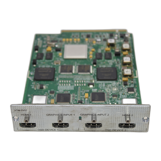
Video Output Module
Quick Reference Guide
The Savant SmartView Video Output Module (VOM-SV02) is used in
the Savant SmartMediaPro family of modular matrix switchers and
controllers. The VOM-SV02 supports a multi-window or tiling
display.
Box Contents
(1)
VOM-SV02
(2)
HDMI Locking Cable (CBL-1LHDMI)
(1)
Quick Reference Guide (this document)
Required System Components
Savant Pro Host
VOM-SV02
Interconnecting Information
After unpacking and installing the module, interconnect the units by
referring to the tables and procedures below.
OSD Device 1 Circuit is formed by:
OSD Device 1 Circuit is formed by:
HDMI output connection to Graphics Input 2
HDMI 1
HDMI input connection from the SVR-xxxx or
Graphics Input 1
the HDMI 2 connection from the previous VOM-
SV02.
OSD Device 2 Circuit is formed by:
OSD Device 2 Circuit is formed by:
Graphics Input 2
HDMI input connection from the HDMI 1
HDMI output connection to Graphics Input 1 on
HDMI 2
next VOM-SV02 or to the HD display
Specifications
Environmental
Environmental
Refer to the SmartMediaPro or SVR chassis specifications
Refer to the SmartMediaPro or SVR chassis specifications
Dimensions and Weight
Dimensions and Weight
Weight
1 lb/0.45 kg (shipping weight)
Power
Power
Power supplied from the SmartMediaPro or SVR chassis.
Power supplied from the SmartMediaPro or SVR chassis.
Compliance
Compliance
Safety and
FCC Part 15 | CE Mark | C-Tick
Emissions
RoHS
Compliant
IMPORTANT! Module Installation Precautions
ELECTRIC DISCONNECT!
Power Off the controller by setting the power switch on the rear
of the chassis to Off (O) and remove the power cord before
inserting or removing any module from the SmartMediaPro
chassis. Failure to do so may cause damage to the equipment.
IMPORTANT! Electrostatic Discharge (ESD) Warning:
VOM-SV02 | 009-0723-02 | 150707
VOM-SV02 | 009-0723-02 | 150707
Copyright © 2015 Savant Systems, LLC
Observe the following precautions to avoid damage from
electrostatic discharge (ESD) when handling modules.
Use an approved ESD wrist or ankle-grounding strap. Ensure the
•
grounding strap makes good skin contact.
Connect the clip end of the ground strap to a threaded grounding
•
stud on the chassis.
When returning a replaced module to Savant, place the module in
•
the clamshell package in which it was originally shipped in or a
static shielding bag.
NOTE:
The wrist strap only protects the component from ESD voltages on
the body; ESD voltages on clothing can still cause damage.
Module Installation
Refer to
Module installation Precautions
module.
1.
Power Off the SmartMediaPro Chassis using the power switch
located on the rear of the chassis and disconnect the AC
power cord.
2.
Remove the two (2) M3 x 6 mm retaining screws. Set screws
aside as they will be used later in procedure.
3.
Align the module board with the two rails located at the
bottom of the opening and gently slide the module all the
way until a slight resistance is felt. This is where the
connector on rear of the board gets seated into the chassis
connector.
4.
Gently press on the module the rest of the way until it seats
into the connector at the rear of the slot and the plate seats
against the chassis.
5.
Insert the screws removed in step 2 and tighten.
Module Removal
Refer to
Module installation Precautions
module.
1.
Power Off the SmartMediaPro Chassis using the power switch
located on the rear of the chassis and disconnect the AC
power cord.
2.
Remove the two (2) M3 x 6 mm retaining screws. Set screws
aside as they will be used later in procedure.
3.
Insert the module removal tool (included with SmartMediaPro
chassis) into the removal tool slot.
For Vertical Removal Slots: Face the notch in the tool
downward and insert the tool into the slot in the module
faceplate.
For Horizontal Removal Slots: Face the notch in the tool to
the left or the right.
4.
Hook the tool onto the faceplate.
For Vertical Removal Slots: Lower the tip of the tool
downward and with slight outward pressure, pull the module
outward. A slight resistance will be felt as the module is
unseated from the chassis side of the connector.
For Horizontal Removal Slots: Move the tool to the left or the
right and with slight outward pressure, pull the module
outward. A slight resistance will be felt as the module is
unseated from the chassis side of the connector.
1
of 2
above before installing
above before removing
45 Perseverance Way, Hyannis, MA 02601
savant.com | 508.683.2500
Advertisement
Table of Contents

Related Manuals for Savant SmartView VOM-SV02


Summary of Contents for Savant SmartView VOM-SV02
- Page 1 Quick Reference Guide (this document) Required System Components Savant Pro Host VOM-SV02 When returning a replaced module to Savant, place the module in • the clamshell package in which it was originally shipped in or a static shielding bag. NOTE: The wrist strap only protects the component from ESD voltages on the body;...
- Page 2 VOM-SV02 | 009-0723-02 | 150707 VOM-SV02 | 009-0723-02 | 150707 45 Perseverance Way, Hyannis, MA 02601 Copyright © 2015 Savant Systems, LLC 2 of 2 savant.com | 508.683.2500...
Need help?
Do you have a question about the SmartView VOM-SV02 and is the answer not in the manual?
Questions and answers