Table of Contents
Advertisement
Quick Links
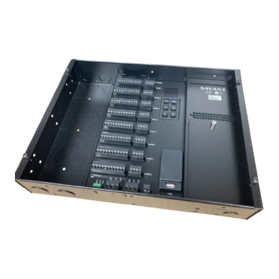
Thermostat Processing Unit (TPU)
CLI-8000-xx
Quick Reference Guide
Box Contents
(1) CLI-8000-xx (Includes all connectors for front panel)
(1) Quick Reference Guide (this document)
Related Components
Savant Host
Savant Controller
External 120V AC to 24V AC Transformer (PWR-2440-xx)
Optional Remote Sensors
SST-TEMP1 - Remote Indoor Sensor
SST-OTEMP1 - Remote Outdoor Sensor
CLI-THFM1 - Remote Humidity/Temperature Smart Sensor
CLI-PLEN1C - Commercial Plenum Sensor (Heat duct sensor)
CLI-PLEN1R - Residential Plenum Sensor (Heat duct sensor)
CLI-SLAB1 - Slab Sensor (Floor Heating Sensor)
Note: Each zone on the CLI-8000 supports communications with up
to four temperature sensors including two humidity sensors.
Specifications
Environmental
Temperature
32° to 104° F (0° to 40° C)
Humidity
10% to 90% (non-condensing)
Dimensions and Weights
without Cover
Height
11.05 in (280.67 mm)
Width
14.23 in (361.44 mm)
Depth
2.71 in (68.83 mm)
Net
Weight
8.75 lb (4.00 kg)
Power
Power (Input)
24V AC (40AV) from external transformer
Power Draw
12W @ 24V AC
(Maximum)
Cable Requirements
18 American Wire Gauge (AWG)
Relay Bank to
Standard HVAC wiring
HVAC system
(RH, RC, W1, W, Y1, Y2, O, G, Aux)
Cable Requirements (Sensors)
Data Sensor
24 AWG (Cat 5) 600 feet
Bus (1-Wire)
(182 m) maximum (cumulative)
Remote Sensor
24 AWG (Cat 5) 500 feet (152 m) maximum
Compliance
Safety and
FCC Part 15
Emissions
RoHS
Compliant
Additional info
RS-232
Baud Rate = 19200
CLI-8000 | 009-1090-03 | 161006
Copyright© 2016 Savant Systems, LLC
Front Panel
with Cover
12.17 in (309.12 mm)
15.48 in (393.19 mm)
2.81 in (71.37 mm)
Shipping
12.00 lb (5.43 kg)
Item
Description
A
Ethernet
Reserved for Future Use
Each relay bank or zone gets wired to an HVAC
B
HVAC Relays
system. Supports wiring up to eight individual
HVAC systems.
Connect cable from the RS-232 port to a Sa-
vant Controller. (Communication between the
C
RS-232
controller and the CLI-8000 is achieved over
the RS-232 connection.) RS-232 supports 19200
baud.
D
Station Bus
Reserved For Future Use
Mini USB (Mini-B) female connector
E
Console
(Serial UART); Debug terminal
Connects to the Data Sensor Bus, which is a
serial bus based on the 1-Wire protocol. The
CLI-THFM1 smart sensor communicates over the
F
DSB/1-Wire
Data Sensor Bus through this connection. Up to
two smart sensors per zone can be configured
with a total of eight per system.
To monitor and configure the system. Use the
G
Display/Keypad
keypad to scroll through the available menus
and configure each zone.
For Indoor, Outdoor, Slab, and Plenum two-wire
H
Remote Sensors
temperature sensors. A maximum of two per
zone is supported.
Remove the power input access screw and
Input Power
remove the associated panel. This will give user
I
(Access)
access to the power supply board for wiring the
24V AC input power.
Indicates which zone has been
J
Zone LEDs
selected via the keypad for configuration.
System is powered by 24V AC power source.
Power cable is fed through ½ inch cable re-
Input Power
K
straint (not included) installed at bottom of box.
(24V AC)
Input power is wired to a two position screw
terminal block on the power supply board.
L
Analog Control
Reserved for Future Use
M
USB
Reserved for Future Use
Maintenance functions such as firmware up-
grades are achieved through the Smart Connect
N
Smart Connect
connection. Requires SCA-CONF-xx or SCA-
CONFL-xx Smart Connect cable.
For Product Info
45 Perseverance Way, Hayannis, MA 02601
Savant.com
| 508.683.2500
Advertisement
Table of Contents

Subscribe to Our Youtube Channel
Related Manuals for Savant CLI-8000 Series


Summary of Contents for Savant CLI-8000 Series
- Page 1 Maintenance functions such as firmware up- grades are achieved through the Smart Connect Smart Connect connection. Requires SCA-CONF-xx or SCA- CONFL-xx Smart Connect cable. CLI-8000 | 009-1090-03 | 161006 45 Perseverance Way, Hayannis, MA 02601 Copyright© 2016 Savant Systems, LLC Savant.com | 508.683.2500...
- Page 2 • CLI-8000 Deployment Guide (009-1073-xx) Note: Use a minimum of 18 AWG wire when connecting the input power. CLI-8000 | 009-1090-03 | 161006 45 Perseverance Way, Hayannis, MA 02601 Copyright© 2016 Savant Systems, LLC Savant.com | 508.683.2500...
Need help?
Do you have a question about the CLI-8000 Series and is the answer not in the manual?
Questions and answers