Table of Contents
Advertisement
Quick Links
Advertisement
Table of Contents

Subscribe to Our Youtube Channel
Related Manuals for IBA ibaClock


Summary of Contents for IBA ibaClock
- Page 1 Time synchronization module for ibaPDA systems Manual Issue 1.4...
- Page 2 However, the information in this publication is updated regularly. Required cor- rections are contained in the following regulations or can be downloaded on the Internet. The current version is available for download on our web site http://www.iba-ag.com. Protection note Windows®...
-
Page 3: Table Of Contents
Manual Table of contents About this manual ................... 5 Target group ....................5 Notations ....................... 5 Used symbols ....................6 Introduction ..................... 7 Scope of delivery .................... 8 Safety instructions ..................9 System requirements ..................10 Hardware ..................... 10 Software ...................... - Page 4 9.3.8 Help ......................35 Configuration with ibaPDA ................36 10.1 First steps ....................36 10.2 ibaClock - "General" tab ................38 10.3 ibaClock - "Digital" tab ................. 39 10.4 ibaClock - "Diagnostics" tab ................. 40 Technical data ....................42 11.1 Main data ....................
-
Page 5: About This Manual
Manual About this manual This manual describes the construction, the use and the operation of the device ibaClock. Target group This manual addresses in particular the qualified professionals who are familiar with han- dling electrical and electronic modules as well as communication and measurement tech- nology. -
Page 6: Used Symbols
Manual ibaClock Used symbols If safety instructions or other notes are used in this manual, they mean: The non-observance of this safety information may result in an imminent risk of death or severe injury: By an electric shock! Due to the improper handling of software products which are coupled to... -
Page 7: Introduction
The following protocols are supported: TIME protocol, DAYTIME pro- tocol and NTP. ibaClock has an internal clock that will carry on to set the time in case of a failure of the GPS signal. Here, ibaClock provides a stability of < 0.150 ppm for temporary signal fail- ures. -
Page 8: Scope Of Delivery
Manual ibaClock Scope of delivery After unpacking, please check the completeness and integrity of the delivery. The scope of delivery comprises: ibaClock device 2-pin connector for power supply 4-pin connector for digital outputs Manual Required accessories: GPS: ... -
Page 9: Safety Instructions
Manual Safety instructions The device is only to be used as shown in the chapter “Technical Data”. Strictly observe the operating voltage range The device is supplied with a voltage of 24 V DC ±10%. When connecting to the voltage, please ensure compliance with the correct power level and polarity. -
Page 10: System Requirements
ibaFOB-io-ExpressCard The firmware of the ibaFOB-D-card must eventually be upgraded to a state D3 or higher for the use of ibaClock. Please contact the iba support in case of a required firmware update. Connection to a standard computer: standard Ethernet cable Software ... -
Page 11: Mounting And Dismounting
7-9 satellites are visible. The antenna should be installed with greatest possible opening angle towards the sky. A mounting rob for the mounting on buildings is available at iba. Other documentation Please find information for positioning and mounting of the antenna in the antenna man- ual. -
Page 12: Device Description
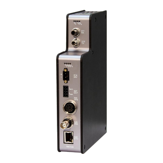
Manual ibaClock Device description Device views 7.1.1 Front view Operating state display FO input (RX) X11 FO output (TX) X10 LEDs for the state of time sources Voltage supply X14 Digital outputs X27 GPS input X44 IRIG-B input X45 Ethernet interface X22... -
Page 13: Display Elements
The 2-pin input serves for the supply of the device with DC 24 V ±10% (non regulated). The operating voltage should be put in via the supplied Phoenix threaded coupling con- nector. If requested, you can also order DIN rails or plug-in power supply units at iba. Issue 1.4... -
Page 14: Digital Outputs
The antenna must be connected with a point-to-point connection to the device. It is recommended to only use the cable which is assembled by iba. When placing the order the required cable length must be indicated (max. 400 m). Due to the technical specification, the use of standard antenna cables is not possible. - Page 15 Manual The NTP and PTP protocols for time synchronization are also available via the Ethernet interface. Issue 1.4...
-
Page 16: System Integration
Several distributed ibaPDA systems can be synchronized exactly at the same time with ibaClock. ibaClock receives the time signal of the GPS satellites; alternatively a IRIG-B or PTP time source can be used. Subsequently the time information is transferred via FO to connected ibaPDA systems. -
Page 17: Time Server Via Network
Manual Time server via network The following protocols are available for time synchronization via network: 8.2.1 TIME Protocol Using this protocol, the time is sent as an unsigned 32-bit integer to the connected de- vice, representing the number of seconds since January 1, 1900, 00:00 GMT. - Page 18 Manual ibaClock 2. Click the menu item „Change date and time settings…“ 3. Click the button <Change settings…> on the Internet time tab. Issue 1.4...
-
Page 19: Ptp
Manual 4. Enter the IP address or the host name in the dialog and click <Update now>. Confirm with <OK >. Note If the PC is operated within a domain, it may be necessary that these settings have to be carried out by the IT department using group policies. - Page 20 Manual ibaClock No further settings have to be made in ibaPDA. As soon as ibaPDA receives PTP telegrams, the BMCA (Best Master Clock Algorithm) determines the best timer in the network and synchronization is carried out. Note When using PTP, please observe the requirements for the network and the built-in com- ponents.
-
Page 21: Initial Start-Up
If the GPS signal fails, the internal clock of the device continues to set the time signal. In this process ibaClock provides a stability of < 0.150 ppm for temporary signal failures. If the GPS signal fails for a longer time (days), deviations of approx. 30 ms are possible per day between two systems which are synchronized with ibaClock. - Page 22 IP addresses. Experience shows that fixed IP addresses are mostly used in the automation area, which means that no DHCP server exists. If DHCP is activated in the network settings of ibaClock, please proceed as follows for establishing a network connection: 1.
- Page 23 Manual 6. Start a web browser on the PC and enter the host name of the device into the URL: e.g. http://ibaclock_000001. For more information, see chapter 9.3.3. Issue 1.4...
-
Page 24: Web Interface
Web interface 9.3.1 Open the web interface 1. Start your web browser if your computer is connected to ibaClock via a bidirectional FO connection, Ethernet or USB. 2. Enter the internet address (URL) of the device into the address line. - Page 25 Manual Figure 4: User detection web interface Default setting for the user credentials: User name: admin Password: 1234 The access should only be available for experienced users to avoid an accidental change of the settings. An accidental change of the network parameters can e.g. cause that the access to the device via Ethernet is no longer possible and that the device parameters have to be reset to the default settings.
-
Page 26: Information - Start Page
Manual ibaClock 9.3.2 Information - start page Figure 5: Start page web interface The basic structure of the websites is identical: (1) Navigation field to select the separate websites. The currently displayed website is shown in green. (2) The actually set time source and its status are displayed in the status bar. The update of the status bar is made automatically. -
Page 27: Network
Manual 9.3.3 Network This page is only accessible after the login over the user “admin”. Figure 6: Web interface network settings This page shows both network adapters the device has. The upper interface „Network interface: Ethernet“ describes the settings of the LAN interface X22, the lower interface „TCP/IP over USB“... -
Page 28: Settings
Manual ibaClock Note Ask the network administrator for a suitable IP address for your network. The following IP addresses are not admitted: 0.0.0.0, broadcast: 255.255.255.255 and localhost addresses (also known as loopback addresses): 127.0.0.0 to 127.255.255.255 as well as the multicast addresses 224.0.0.0 to 239.255.255.255 (224.0.0.0/4). - Page 29 Manual Issue 1.4...
- Page 30 Manual ibaClock PTP settings: Issue 1.4...
-
Page 31: Gps
Manual 9.3.5 Figure 8: Web interface GPS Status: GPS Time: Time in seconds since 1 January 1970 00:00 UTC GPS Antenna: Indicates whether the GPS antenna is connected. GPS Signal: Indicates the status of the GPS signal. -
Page 32: Ptp
Manual ibaClock Satellites in use: Number of satellites that are used for time determination. Satellites: The list of satellites with their ID, elevation and azimuth angle as well as the signal strength in dB and whether they are being used at this moment. - Page 33 Manual P2P (Peer-to-Peer) mechanism If only PTP-capable components are installed in the network and they are config- ured so that they can use the same mechanism, this setting can then be used to detect the propagation delay. Network Transport: This settting is used to determine the communication layer in the network on which the PTP synchronization occurs.
-
Page 34: Administration
This makes it difficult for unauthorized persons to access administrative properties. Firmware update 1. Click on the <Browse...> button and select the update file <clock_ v[xx.yy.zzz].iba>. 2. By clicking on <Start Update>, you start the update. The update progress is displayed in the status bar. -
Page 35: Help
Manual Note If a firmware update should be necessary, please contact the iba support. You will then receive the corresponding data and further information about the update. Important note The firmware update takes a few minutes. The device must certainly not turned off during... -
Page 36: Configuration With Ibapda
Manual ibaClock Configuration with ibaPDA To be able to use ibaClock together with ibaPDA, the device must be configured in the I/O Manager of ibaPDA. Requirements: ibaPDA, version 6.34.0 or higher Firmware of the ibaFOB-D card: D3 or higher If ibaClock is connected to an ibaPDA system, the device sends the UTC time to ibaPDA. - Page 37 3. You can also manually add the device. Click the right mouse button on the link of the ibaFOB card the device shall be connected to and select “Add module” and “ibaClock” from the displayed list. The device will be displayed in the signal tree. 4. Configure the “ibaClock” module in the I/O Manager. Issue 1.4...
-
Page 38: Ibaclock - "General" Tab
Manual ibaClock 10.2 ibaClock - "General" tab Figure 12: ibaClock – “General“ tab Basic settings Module Type Display of the module type, cannot be changed. Locked True: the module can be changed by authorized users only. False: the module can be changed by all users. -
Page 39: Ibaclock - "Digital" Tab
10.3 ibaClock - "Digital" tab Figure 13: ibaClock – “Digital“ tab In the “Digital” tab, the status signal of the time source can be activated. Name The signal name is already given. You can insert two additional comments if you click the symbol in the signal name field. -
Page 40: Ibaclock - "Diagnostics" Tab
Write firmware Using the <Write firmware> button, it is possible to run firmware updates. Select the update file „clock_v[xx.yy.zzz].iba“ in the browser and start the update with <OK>. Important note This procedure can take a few minutes and must not be interrupted. - Page 41 Clock source: selected time source Clock source status: Display if ibaClock sends a valid time Clock status: ibaClock will not synchronize with the ibaFOB-D card before the con- figuration has not been applied from ibaClock to ibaPDA. When the synchronization is done, the bar changes its color to green and displays a corresponding status message.
-
Page 42: Technical Data
Manual ibaClock Technical data 11.1 Main data Manufacturer iba AG, Germany Order number 10.160000 Description Universal time server Time sources Supported GPS antenna: Smart antenna Trimble Acutime GG / Acutime 360; power supply via ibaClock Antenna precision: 15 ns (static) - Page 43 Manual Fiber optics Time synchronization, configuration and diagnos- tics Ethernet RJ45 socket (Ethernet 10/100 Mbit/s) for configura- tion and diagnostics Simulation Time server function without active time source (e.g. commissioning, etc.) Freewheel accuracy High-precision with PLL-controlled internal quartz generator Buffered RTC (Real Time Clock) for approx.
-
Page 44: Dimension Sheet
Manual ibaClock 11.2 Dimension sheet (Dimensions in mm) Figure 15: Dimension sheet Thread of the antenna holder Thread in the antenna holder: ¾” 14-NPT pipe thread Issue 1.4... -
Page 45: Pin Assignment Antenna Cable
Manual 11.3 Pin assignment antenna cable Assignment of the connector at antenna side - connector ibaClock side Antenna connector* Connector for ibaClock (X44)* Manufacturer description: IMC26-2212X (12 size 22) (DIN 45326) Antenna Function Protocol ibaClock Function Pin 1... - Page 46 Manual ibaClock Accessories and connectors for the cable assembly If you want to assemble the cable by yourself, some special accessories are necessary. You can order the accessories or connectors at Farnell via de.farnell.com, for example. Manufacturer no. Description 6862-201-22278...
-
Page 47: Accessories
30 minutes, subsequent to a 3-days sig- nal failure. The GPS antenna downloads an almanac and does not supply a signal Distribution of the ibaClock FO via The firmware of the data distributor must ibaBM-FOX-i-3o-D or be upgraded. ibaBM-DIS-i-8o does not work... -
Page 48: Antenna Configuration
13.1 Antenna configuration If you have not purchased the antenna from iba, it will still be provided with the manufac- turer’s delivery configuration. 1. Connect the antenna with the Trimble RS-422 to USB converter (included in the starter kit) and connect these to the PC. - Page 49 Manual c. Click “Set” to accept the changes. d. Click on “Save Configuration” to make the changes permanent. 7. The configuration is complete. Issue 1.4...
-
Page 50: Security
Continuously advanced attack techniques in the field of IT as well as ever-new security gaps in proprietary as well as open-source software or hardware make unauthorized network accesses easier. It is therefore recommended to connect network-capable iba devices to untrusted networks only with sufficient protection, such as a firewall. -
Page 51: List Of Ports Used
In addition to the web interface, the device also has the following accesses. Telnet A telnet service runs on the service and fiber optic interface. In support cases, this can be used by the iba support to get more accurate information about the error sit- uation. FTP An FTP server for transmitting update files is active on the service and fiber optic interface. -
Page 52: Ptp
Manual ibaClock 15.1 Functional principle Similar to NTP, PTP synchronization messages can also be exchanged between the nodes involved. PTP defines the nodes involved as masters or slaves. NTP, on the other hand, defines the nodes as servers and clients. -
Page 53: Network Requirements
Manual The offset that is used to correct the slave clock is calculated as follows. ������������ = ���������������������� �������������������� − ������ − �������� (�� − �� + �� − �� ������������ = ( �� ) − − �� However, this calculation of the offset is only correct on the assumption that a constant propagation speed prevails in the network. - Page 54 Manual ibaClock Figure 18: Exemplary PTP environment with a transparent clock Figure 19: Boundary Clock Issue 1.4...
-
Page 55: Ntp
Manual Since NTP was developed for synchronization over long distances (wide area networks = WANs), it does not place any particular requirements on the network infrastructure. In the event of a synchronization via WANs, such as the Internet, NTP can be used to achieve an accuracy of about 0.01 seconds. - Page 56 Manual ibaClock Figure 21: NTP time stamp exchange The client (peer A) sends the time stamp T1 to the server (peer B). Then the server sends the client a message containing the time stamp T1 (sending time from the client), T2 (receiving time at the server) and T3 (sending time from the server).
-
Page 57: Support And Contact
Fax: +49 911 97282-33 E-mail: iba@iba-ag.com Contact: Harald Opel Shipping address iba AG Gebhardtstr. 10 DE-90762 Fürth Germany Regional and Worldwide For contact data of your regional iba office or representative please refer to our web site www.iba-ag.com. Issue 1.4...
Need help?
Do you have a question about the ibaClock and is the answer not in the manual?
Questions and answers