Table of Contents
Advertisement
Quick Links
Advertisement
Table of Contents

Related Manuals for IBA ibaMS16xDO-2A


Summary of Contents for IBA ibaMS16xDO-2A
- Page 1 Output module for digital signals Manual Issue 1.3...
- Page 2 However, the information in this publication is updated regularly. Re- quired corrections are contained in the following regulations or can be downloaded on the Inter- net. The current version is available for download on our web site www.iba-ag.com. Copyright notice Windows ®...
-
Page 3: Table Of Contents
Manual Table of contents About this manual ................... 5 Target group ....................6 Notations ....................... 6 Used symbols....................7 Introduction ..................... 8 Scope of delivery..................... 8 Safety instructions ..................9 Proper use ....................9 Special safety instructions ................9 System requirements .................. - Page 4 Update via ibaPDA ..................24 Module Information / Diagnostics ..............25 9.4.1 Diagnostics in ibaPDA ................. 25 9.4.2 Web interface ....................25 iba applications ..................... 27 10.1 Configuration in ibaPDA ................27 10.1.1 General settings ..................27 10.1.2 Output configuration ..................29 10.1.3...
-
Page 5: About This Manual
Manual About this manual In this manual, you learn a lot about the design of the ibaMS16xDO-2A module and how to use and operate it. You can find a general description of the systems of the iba-mod- ular system and further information about the design of the central units and how to use and operate them in separate manuals. -
Page 6: Target Group
Manual ibaMS16xDO-2A Target group This manual addresses in particular the qualified professionals who are familiar with han- dling electrical and electronic modules as well as communication and measurement tech- nology. A person is regarded to as professional if he/she is capable of assessing safety and recognizing possible consequences and risks on the basis of his/her specialist training, knowledge and experience and knowledge of the standard regulations. -
Page 7: Used Symbols
Manual Used symbols If safety instructions or other notes are used in this manual, they mean: The non-observance of this safety information may result in an imminent risk of death or severe injury: • By an electric shock! Due to the improper handling of software products which are coupled to input •... -
Page 8: Introduction
Introduction The ibaMS16xDO-2A module is part of the iba-modular system. The modular concept is based on a backplane with a backplane bus. On this backplane bus, you can plug a central unit and up to 4 input/output modules. The power supply of the module is provided by the backplane bus. -
Page 9: Safety Instructions
Manual Safety instructions Proper use This device is used for the output of digital signals. It is only allowed to use the device in combination with a central unit (e.g. ibaPADU-S-IT-2x16 or ibaPADU-S-CM). The device is only to be used as shown in the „Technical Data“. -
Page 10: System Requirements
Manual ibaMS16xDO-2A System requirements Hardware Central unit: ibaPADU-S-IT-2x16 or ibaPADU-S-CM (version 02.10.001 or later) Backplane unit, e.g. ibaPADU-B4S Software ibaPDA version 6.34.0 or later ibaLogic-V5 version 5.0.2 or later Note The use of ibaLogic-V5 requires the central unit ibaPADU-S-IT-2x16. If the module is used with the predecessor ibaPADU-S-IT-16, only ibaLogic-V4 can be used. -
Page 11: Connecting
Manual Connecting Note The backplane unit and the device must be connected to a protective conductor. 1. Connect all cables. 2. If all required cables are connected, connect the central unit to the power supply. 3. Switch on the voltage supply of the central unit. -
Page 12: Device Description
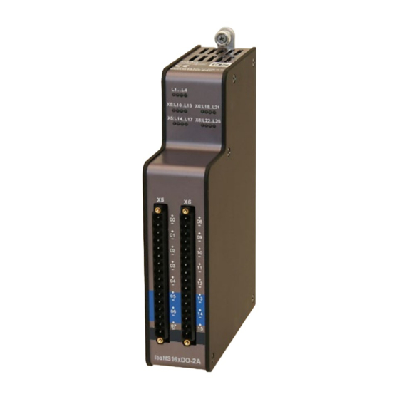
Manual ibaMS16xDO-2A Device description Device views Fixing screws Operating status indicators L1 … L4 Status LEDs L10 … L25 for the digital outputs 00 … 15 Connector X5 for digital outputs 00 … 07 Connector X6 for digital outputs 08 … 15... -
Page 13: Indicator Elements
L2: yellow Access to the backplane bus L3: white L4: red Normal status, no faults Disorder/Fault Important note When LED L4 indicates a failure, please contact the iba support. 7.2.2 Status of digital outputs L10 … L25 LED* Status Description L10…L25... -
Page 14: Digital Outputs
Manual ibaMS16xDO-2A Digital outputs 7.3.1 Connection diagram / Pin assignment 16 output signals (0...15), each bipolar and electrically isolated, can be connected. Each channel is connected by means of two-wire-connection. Figure 3: Connection diagram Issue 1.3... -
Page 15: Circuit Design
Manual Pin assignment X5 Pin Connection X6 Pin Connection Digital output 00 + Digital output 08 + Digital output 00 − Digital output 08 − Digital output 01 + Digital output 09 + Digital output 01 − Digital output 09 −... -
Page 16: Output Channel As P Switch
Manual ibaMS16xDO-2A 7.3.3 Output channel as P switch The circuit is designed as P switch (positive voltage). The connected load Z is connected to –U and switched on +U by means of the controllable switch (load switch) in the output channel. In the figure below, you can see this typical circuit. -
Page 17: Output Channel With External Diodes
Manual 7.3.5 Output channel with external diodes For load circuits with P switch: Figure 6: Output channel with external diodes and P switch For load circuits with N switch: Figure 7: Output channel with external diodes and N switch... -
Page 18: Connectors
Manual ibaMS16xDO-2A When connecting a freewheeling diode: Figure 8: Optimum wiring with a freewheeling diode Connectors 7.4.1 Grounding screw X29 Proper connection of cable shielding to the device should be ensured. The shield con- nector (M6 screw) found on the bottom of the device should be connected with any total shield that serves for all sensor cables. -
Page 19: Protective And Monitoring Functions
Manual Protective and monitoring functions Physical protective functions of the hardware Important note The protective functions are only guaranteed when the polarity is correct. The output channels have several self-protective functions for preventing damages to the device even when there are faults in the load circuit. -
Page 20: Toleration Of Inductive Loads
Manual ibaMS16xDO-2A 8.1.5 Toleration of inductive loads Note For inductive loads, the self-protection is only for preventing the direct destruction of the load switch by rebound voltages that are too high. The rebound energy heats up the load switch. There is no over temperature protection for this problem. This is why circuiting with inductive loads needs to be planned carefully, considering all failure sce- narios. -
Page 21: Monitoring Functions / Error States
Manual Monitoring functions / Error states Monitoring functions are used to identify error states of the channels and the device. The following error types are monitored on each channel and indicated by a status signal in ibaLogic. Shorted switch ... -
Page 22: Overcurrent
Manual ibaMS16xDO-2A 8.2.4 Overcurrent The current of the channel load circuit has exceeded half of the current that is admissible for the protective function of the fuse. If a current is flowing that is too high, the IC switch switches off internally. The magnitude of the current depends on the number of impulses and the energy over time. -
Page 23: Start-Up / Update
Support. Overall Release Version The „Overall Release Version“ provides information about the software version of the entire iba-modular system. You can find it on the Website of the central unit or in the I/O Manager of ibaPDA. Important note If you require support, please specify the „Overall Release Version“. -
Page 24: Update
Important note The Web interface is available only with the central unit ibaPADU-S-IT-2x16. Start the Website of the iba-modular system in your browser and select the central unit. On the “update“ tab, click on the <Browse…> button and choose the <padusit2x16_ v[xx.yy.zzz].iba>... -
Page 25: Module Information / Diagnostics
Important information about the iba-modular system, like hardware version, firmware ver- sion, FPGA version and serial number is displayed in the “Diagnostics” tab. Open the ibaPDA I/O Manager and choose your iba-modular system in the tree structure (see also the figure above) 9.4.2... - Page 26 Manual ibaMS16xDO-2A 9.4.2.1 „info“ tab The „info“ tab displays general information and technical specifications of the I/O module. Figure 11: „info“ tab 9.4.2.2 „notes“ tab On the „notes“ tab, you can enter notes, e.g. for notes on wiring or the recording of changes.
-
Page 27: Iba Applications
The automatic detection requires a bidirectional FO connection from the ibaPDA com- puter to the central unit. Other documentation If you want to install the iba-modular system at first, refer to the manual of the central unit, chapter “Configuration with ibaPDA”. 10.1.1 General settings If the module is detected, click on the module in the signal tree and the “General”... - Page 28 Manual ibaMS16xDO-2A Locked True: the module can only be changed by an authorized user. False: the module can be changed by any user. Enabled Data capturing for this module is enabled. Name You can enter a name for the module.
-
Page 29: Output Configuration
Manual 10.1.2 Output configuration Select the „Output“ menu in order to configure settings and signals at the output side. The following settings apply to the “Digital” tab: Figure 15: I/O-Manager ibaM162xDO-2A - Outputs Digital tab Name You can enter a name for the signal and two additional comments (click on the icon in the Name field). - Page 30 Manual ibaMS16xDO-2A Figure 16: Outputs - „Reset channel errors“ Name You can enter a name for the signal and two additional comments (click on the icon in the Name field). Expression Using the expression builder you can specify an output signal in order to reset a hardware error.
-
Page 31: Diagnostics Channels
Diagnostics channels In the „Hardware“ menu, status and error signals can be activated in the “Digital” tab: Figure 17: I/O-Manager ibaMS16xDO-2A - Hardware - Digital tab Name Status signals can be activated here. They have default names, but you can enter two additional comments (click on the icon in the Name field). -
Page 32: Configuration In Ibalogic-V5
The signals can be configured in the I/O Configurator of ibaLogic-V5. Open the I/O Con- figurator in the “Configuraton – I/O Configurator“ menu. When you click on the <Update Hardware> button, then ibaLogic detects the module. ibaMS16xDO-2A offers the following signal groups: 1. Outputs 2. Inputs The digital output channels as well as the ResetErrors are shown under „Outputs“. - Page 33 Manual All available status or failure information is listed under „Inputs“. Figure 19: ibaMS16xDO-2A inputs Issue 1.3...
- Page 34 Manual ibaMS16xDO-2A Signal Description Inputs DO_On_Ch[00…15] Channel status: 0 = channel not ready for operation 1 = channel ready for operation DO_Err_Ch[00...15] Group error per channel of „DO_Err_OverCur- rent_Ch[00…15]“ and „DO_Err_Over- Temp_Ch[00…15]“. Failure remains active until it is set back by means of „ResetError_Ch[00…15]“.
-
Page 35: Technical Data
Manual Technical Data 11.1 Main Data Short description Name ibaMS16xDO-2A Description Output module with 16 digital outputs Order number 10.124250 Power supply, interfaces, Voltage supply 24 V DC, internal via backplane bus Power consumption Max. 8 W Operating and indicating elements... -
Page 36: Digital Outputs
Supplier's Declaration of Conformity 47 CFR § 2.1077 Compliance Information Unique Identifier: 10.124250 ibaMS16xDO-2A Responsible Party - U.S. Contact Information iba America, LLC 370 Winkler Drive, Suite C Alpharetta, Georgia 30004 (770) 886-2318-102 www.iba-america.com FCC Compliance Statement This device complies with Part 15 of the FCC Rules. Operation is subject to the following two conditions: (1) This device may not cause harmful interference, and (2) this device must ac- cept any interference received, including interference that may cause undesired operation. -
Page 37: Dimensions
Manual Permanent overcurrent protec- min. >2.0 / typ. 2.3 / max. <2.7A tion Surge current protection Channel inactive at an impulse of appr. 3 A x 80 ms/ 5 A x 33 ms/ 10 A x 15 ms/20 A x 7 ms... -
Page 38: Support And Contact
Mailing address iba AG Postbox 1828 D-90708 Fuerth Germany Delivery address iba AG Gebhardtstrasse 10 DE-90762 Fuerth Germany Regional and Worldwide For contact data of your regional iba office or representative please refer to our web site www.iba-ag.com. Issue 1.3...
Need help?
Do you have a question about the ibaMS16xDO-2A and is the answer not in the manual?
Questions and answers