Table of Contents
Advertisement
Quick Links
Advertisement
Table of Contents

Related Manuals for IBA ibaMS4xAI-380VAC


Summary of Contents for IBA ibaMS4xAI-380VAC
- Page 1 Input module for analog signals Manual Issue 1.5...
- Page 2 However, the information in this publication is updated regularly. Re- quired corrections are contained in the following regulations or can be downloaded on the Inter- net. The current version is available for download on our web site www.iba-ag.com. Copyright notice Windows is a label and registered trademark of the Microsoft Corporation.
-
Page 3: Table Of Contents
Update via Web Interface ................17 8.3.2 Update via ibaPDA ..................17 Module Information / Diagnostics ..............18 8.4.1 Diagnostics ....................18 8.4.2 Web Interface ....................18 iba Applications ..................... 20 Configuration in ibaPDA ................20 9.1.1 “General” tab ....................20 Issue 1.5... - Page 4 Manual ibaMS4xAI-380VAC 9.1.2 “Analog” tab ....................22 9.1.3 „Grid frequency [10Hz..80Hz]“ tab ............... 23 Configuration in ibaLogic-V5 ............... 25 9.2.1 Configuring signals ..................25 9.2.2 Additional functions ..................27 Technical Data ....................29 10.1 Main data ....................29 10.2 Analog inputs ....................30 10.3...
-
Page 5: About This Manual
Manual About this manual In this manual, you learn a lot about the design of the ibaMS4xAI-380VAC device and how to use and operate it. You can find a general description of the iba-modular system and further information about the design of the central units and how to use and operate them in separate manuals. -
Page 6: Target Group
Manual ibaMS4xAI-380VAC Target group This manual addresses in particular the qualified professionals who are familiar with han- dling electrical and electronic modules as well as communication and measurement tech- nology. A person is regarded to as professional if he/she is capable of assessing safety and recognizing possible consequences and risks on the basis of his/her specialist training, knowledge and experience and knowledge of the standard regulations. -
Page 7: Used Symbols
Manual Used symbols If safety instructions or other notes are used in this manual, they mean: The non-observance of this safety information may result in an imminent risk of death or severe injury: • By an electric shock! •... -
Page 8: Introduction
You can plug on this backplane not only the CPU, but also up to 4 input/output modules. The power supply of the I/O mod- ules is provided by the backplane bus. The ibaMS4xAI-380VAC module offers 4 analog inputs. -
Page 9: Safety Instructions
Capturing of measuring data Automation of industrial plants Applications with iba products (ibaPDA, ibaLogic etc.) The device is only to be applied as shown in the Technical Data. Special safety instructions Strictly observe the measuring range (see Technical Data)! -
Page 10: System Requirements
Manual ibaMS4xAI-380VAC System Requirements Hardware Central unit: ibaPADU-S-IT-2x16 or ibaPADU-S-CM (version 02.10.001 or later) Backplane unit, e. g. ibaPADU-B4S Software ibaPDA version 6.34.0 or later ibaLogic-V5 version 5.0.2 or later Note The use of ibaLogic-V5 requires the central unit ibaPADU-S-IT-2x16. If the module is used with the predecessor ibaPADU-S-IT-16, only ibaLogic-V4 can be used. -
Page 11: Connecting
Manual Connecting Note The backplane unit and the device must be connected to a protective conductor. 1. Connect all cables. 2. If all required cables are connected, connect the central unit to the power supply. 3. Switch on the central unit. -
Page 12: Device Description
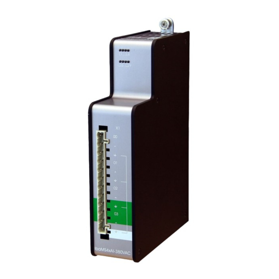
Manual ibaMS4xAI-380VAC Device description Views Fixing screws Operating status indicators L1 to L4 Status LEDs L26 to L29 of the analog inputs 00 to 03 Connector X1 for analog inputs 00 to 03 Figure 1: Front view Grounding screw Figure 2: Bottom view... -
Page 13: Indicator Elements
Access to the backplane bus L3: white L4: red Normal status, no faults Flashing Device failure Important note When the LED L4 indicates a failure, please contact the iba Support. 7.2.2 Status of analog inputs LED per Status/meaning Description (approx. values) channel L26 …... -
Page 14: Grid Frequency Measurement
Manual ibaMS4xAI-380VAC Figure 3: Filter sections principle 7.3.2 Grid frequency measurement Each channel provides grid frequency measurement. Note In addition to the actual measured values, the grid frequency signals are available as virtual signals in the signal tree and can be displayed, recorded and used for calculations... -
Page 15: Connection Diagram / Pin Assignment
Manual 7.3.3 Connection diagram / pin assignment Here, you can connect 4 input signals (0 ... 3), each bipolar and electrically isolated. Each channel is connected by means of two-wire connection. Figure 4: Connection diagram Pin assignment X1: Pin... -
Page 16: Start-Up / Update
Support. Overall Release Version The „overall release version“ provides information about the software version of the en- tire iba-modular system. You can find it on the Website of the central unit or in the I/O Manager of ibaPDA. Important note If you require support, specify the „overall release version“. -
Page 17: Update Via Web Interface
Important note The Web interface is available only with the central unit ibaPADU-S-IT-2x16. Start the Website of the iba-modular system in your browser and select the central unit. On the “update“ tab, click on the <Browse…> button and choose the <padusit2x16_ v[xx.yy.zzz].iba>... -
Page 18: Module Information / Diagnostics
Important information about the iba-modular system, like hardware version, firmware ver- sion, FPGA version and serial number is displayed in the “Diagnostics” tab. Open the ibaPDA I/O Manager and choose your iba-modular system in the tree structure (see also the figure above). - Page 19 Manual 8.4.2.2 „notes“ tab On the “notes“ tab, you can enter notes, e.g. for notes on wiring or on recording of changes. By clicking on <save notes>, the notes are permanently stored on the device. Figure 8: „notes“ tab...
-
Page 20: Iba Applications
The automatic detection requires a bidirectional FO connection from the ibaPDA com- puter to the central unit. Other documentation If you want to install the iba-modular system at first, refer to the manual of the central unit, chapter “Configuration with ibaPDA”. 9.1.1 “General”... - Page 21 Manual Locked True: the module can only be changed by an authorized user. False: the module can be changed by any user. Enabled Data capturing for this module is enabled. Name You can enter a name for the module.
-
Page 22: Analog" Tab
9.1.2 “Analog” tab The following settings apply to the “Analog” tab: Figure 11: I/O Manager ibaMS4xAI-380VAC – Analog tab Name You can enter a name for the signal and two additional comments (click on the icon in the Name field). -
Page 23: Grid Frequency [10Hz
„Grid frequency [10Hz..80Hz]“ tab When grid frequency measuring is enabled, this tab appears additionally. Figure 12: I/O-Manager ibaMS4xAI-380VAC - Grid frequency [10Hz..80Hz] tab Name You can enter a name for the signal and two additional comments (click on the icon in the Name field). - Page 24 Manual ibaMS4xAI-380VAC Interval You can select the measuring interval via a dropdown menu: 1s or 10 s (according to DIN EN 61000-4-30). Active Enabling/disabling the signal. You can show or hide more columns via the context menu (click with the right mouse button in the headline).
-
Page 25: Configuration In Ibalogic-V5
“Tools – I/O Configurator“ menu. When you click on the <Update hard- ware> button, then ibaLogic detects the module. Figure 13: Inputs ibaMS4xAI-380VAC The analog input channels and the grid frequency signals are displayed in the „Inputs“... - Page 26 Manual ibaMS4xAI-380VAC Figure 14: Outputs ibaMS4xAI-380VAC The filters are enabled and configured by means of signal outputs as well as the mode for grid frequency measurement. If “Buffered Access“ is enabled, you can see additional input and output signals. Note You need to apply the “Buffered Access“...
-
Page 27: Additional Functions
Manual Signals Description Outputs DigitalFilterMode Activates the digital anti-aliasing filter in addition to the analog anti-aliasing filter (if activated) AntiAliasingFrequency Setting of the cutoff frequency of the digital anti-aliasing filter EnableFilter_Ch[00…03] Enables the analog anti-aliasing filters (per channel) PwrFrqMode_Ch[00…03]... - Page 28 Manual ibaMS4xAI-380VAC Meaning of the default values for the anti-aliasing filter: FALSE switched-off TRUE switched-on Now, connect the OTC and the signal on the margin of the programming surface. Figure 17: Connecting Off-task connector The configuration of the following functions is similar to the analog filter configuration as described above.
-
Page 29: Technical Data
Manual Technical Data 10.1 Main data Short description Name ibaMS4xAI-380VAC Description Input module with 4 analog voltage inputs Order number 10.124521 Power supply Power supply 24 V DC, internal via backplane bus Power consumption max. Indicating elements Indicators (LEDs) -
Page 30: Analog Inputs
Supplier's Declaration of Conformity 47 CFR § 2.1077 Compliance Information Unique Identifier: 10.124521 ibaMS4xAI-380VAC Responsible Party - U.S. Contact Information iba America, LLC 370 Winkler Drive, Suite C Alpharetta, Georgia 30004 (770) 886-2318-102 www.iba-america.com FCC Compliance Statement This device complies with Part 15 of the FCC Rules. Operation is subject to the following two conditions: (1) This device may not cause harmful interference, and (2) this device must accept any interference received, including interference that may cause undesired operation. -
Page 31: Additional Functions
Manual 10.3 Additional functions Additional functions Grid frequency measurement Interval 10 Hz…80 Hz 1 s / 10 s (according to DIN EN 61000-4-30) 10.4 Dimensions Figure 18: Module dimensions (dimensions in mm) Issue 1.5... -
Page 32: Support And Contact
Mailing address iba AG Postbox 1828 D-90708 Fuerth Germany Delivery address iba AG Gebhardtstrasse 10 DE-90762 Fuerth Germany Regional and Worldwide For contact data of your regional iba office or representative please refer to our web site www.iba-ag.com. Issue 1.5...
Need help?
Do you have a question about the ibaMS4xAI-380VAC and is the answer not in the manual?
Questions and answers