Table of Contents
Advertisement
Quick Links
ASSEMBLY AND OPERATION
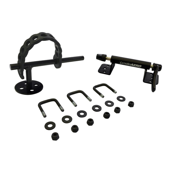
PARTS LIST
Qty Description
A
1
Rear Wheel Stop
B
3
U-Bolts
C
6
Steel Nuts & Washers
D
1
Fork Mount Assembly
Preparation:
Using the Fork-IT Bicycle mount system (sold
individually; one kit per bike), multiple bikes can be
transported on the GearCage Cargo Carrier (or other
rooftop & hitch carriers with 1 inch railings or Yakima/
Thule compatible bars) with numerous mounting
options for placement.
See the Bicycle Position Overview on Pages 4 and 5 before beginning assembly to plan for bicycle position
before installation of Fork-IT system. Final placement will depend on number of bicycles to be transported,
intended interior cargo and user preference.
Step 1:
The Fork Mount Assembly [D] has the option to be mounted to either the Top or Side of the GearCage railing.
[See Figures 1 & 2 for Top Mount illustration; See Figures 3 & 4 for Side Mount illustration].
Install the Fork Mount to the GearCage railing in the desired position using four (4) Steel Nuts and Washers
[C] and two (2) U-Bolts [B] as shown. Do not fully secure connections at this time, hand-tighten only until
final bike fit is complete.
Top Rail Mount
[Figure 1]
D
C
B
[Figure 2]
D
C
B
Page 1 of 6
GearCage
A
C
Side Rail Mount
[Figure 3]
B
D
C
Fork-IT™
Part No. H01793
Bicycle Fork Mount Kit for
Brand Cargo Carriers
®
*For Skewer Mount Only (Not Thru Axle)
B
D
[Figure 4]
C
B
D
FI Manual-073117
Copyright © 2017 Lets Go Aero Inc.
Advertisement
Table of Contents

Subscribe to Our Youtube Channel
Related Manuals for Let's Go Aero Fork-IT H01793


Summary of Contents for Let's Go Aero Fork-IT H01793
- Page 1 Fork-IT™ Part No. H01793 Bicycle Fork Mount Kit for GearCage Brand Cargo Carriers ® ASSEMBLY AND OPERATION *For Skewer Mount Only (Not Thru Axle) PARTS LIST Qty Description Rear Wheel Stop U-Bolts Steel Nuts & Washers Fork Mount Assembly Preparation: Using the Fork-IT Bicycle mount system (sold individually;...
- Page 2 Step 2: Install the Rear Wheel Stop using two (2) [Figure 5] [Figure 6] Steel Nuts and Washers [C] and one (1) U-Bolt [B] as shown with the Rear Stop [A] resting on top of the GearCage rails and the U-Bolt [B] secured from underneath as shown.
- Page 3 Operation: With the bicycle rear tire resting against the Rear Wheel Stop’s “Peg”, stretch the Adjustable Rubber Strap with the Hammerhead end through the tire and reconnect to a hole position that is one hole tighter than unstreched [Figure 9 & 10]. NOTE: The Adjustable ADJUSTABLE Strap should be taut...
- Page 4 Bicycle Position Overview: It is highly recommended to plan your bicycle placement before installing the Fork-IT mount assembly. Below are some examples of Fork-IT Mount and bicycle placement on the GearCage carrier. NOTE: Example placement has been organized for maximized cargo space; actual placement may vary depending on the number of bicycles, cargo, and sizes of the bicycles to be transported.
- Page 5 Bicycle Position Overview: GearCage FP-6 Including the bicycles positions available on Page 4 the GearCage FP-6 has more available configurations for multiple bicycle transport. Below are some expanded examples of Fork-IT Mount and Bicycle placement that are possible on the GearCage FP-6 only. NOTE: For clearance purposes, never allow the carrier, bicycles and fork mount apparatus to exceed the width of the tow vehicles mirrors.
- Page 6 Warranty Information ONE YEAR LIMITED WARRANTY Let’s Go Aero warrants this product to be free from defect in material and workmanship for one year (retain your sales receipt for your records). Any product or part thereof found to be defective within that period will be replaced without charge provided that: (1) the prod- uct was not misused;...
Need help?
Do you have a question about the Fork-IT H01793 and is the answer not in the manual?
Questions and answers