Table of Contents
Advertisement
Quick Links
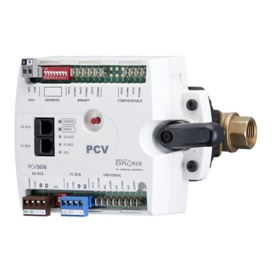
FX-PCV1656 Programmable VAV Box VAV Controllers
Installation Instructions
Applications
The FX-PCV1656 controller with ball valve linkage is
intended to be field mounted to Johnson Controls®
VG1000 Series Ball Valves 1/2 through 1 in. (ordered
separately). The controller is well suited for applications
such as chilled beams and fan coils. The FX-PCV1656
controller is for use on Johnson Controls VG1000 1/2
through 1 in. valves only.
Important: Use this FX-PCV1656 controller only to
control equipment under normal operating
conditions. Where failure or malfunction of
the FX-PCV1656 controller could lead to
personal injury or property damage to the
controlled equipment or other property,
additional precautions must be designed
into the control system. Incorporate and
maintain other devices, such as supervisory
or alarm systems or safety or limit controls,
intended to warn of or protect against failure
or malfunction of the FX-PCV1656
controller.
Switchable Communications
Protocols
By default, the FX-PC family controllers and network
sensors communicate using the standard BACnet®
protocol, based on the ANSI/ASHRAE 135-2004.
The BACnet protocol is a standard for ANSI, ASHRAE,
and the International Standards Organization (ISO) for
building controls.
FX-PCV controllers are BTL-tested and listed as BACnet
Application Specific Controllers (B-ASCs).
FX-PCV1656 Programmable VAV Box VAV Controllers Installation Instructions
Part No. 24-10143-829, Rev. A
Refer to the
QuickLIT website
Release 10.1 and higher of FX-PCT can be used to switch
the Field Bus communications protocol in FX-PC
Controllers to be either the standard BACnet®
Master-Slave/Token-Passing (MS/TP) or the N2 protocol.
BACnet MS/TP is the default communications protocol
for all new controllers. Switchable communications
protocols provide a cost-effective upgrade and
modernization path for customers with existing N2
controllers. The Modernization Guide for Legacy N2
Controllers (LIT-12012045) and the controller-specific
documentation provide installation and commissioning
support and include tips for efficient and safe
replacement. Refer to the N2 Compatibility Options
chapter of the Controller Tool Help (LIT-12011147) for
information about mapping N2 Objects in controllers with
switchable communications protocols.
The N2-capable FX-PC controllers can be used as
functional replacements for legacy N2 controllers. The
N2-capable FX-PC controllers:
•
have the I/O quantities and characteristics of the
FX-PC family controllers
•
must be programmed with FX-PCT, which has
programming capabilities that are similar (but not
identical) to HVACPro, GX9100, GPL, and other
legacy tools
•
support SA Bus devices
•
support FX-WRZ wireless sensors from the controller
using the FX-WRZ7860 receiver when configured for
BACnet MS/TP communication
The N2-capable FX-PC controllers:
•
do not support Zone Bus (for example, TMZ sensors
and M100 actuators)
•
do not support passthrough in the commissioning
mode
•
do not support remote downloading or commissioning
using BACnet routing
•
do not support wireless connection to the N2 bus
Issued April 2016
for the most up-to-date version of this document.
1
Advertisement
Table of Contents

Subscribe to Our Youtube Channel
Related Manuals for Johnson Controls FX-PCV1656


Summary of Contents for Johnson Controls FX-PCV1656
- Page 1 Master-Slave/Token-Passing (MS/TP) or the N2 protocol. separately). The controller is well suited for applications BACnet MS/TP is the default communications protocol such as chilled beams and fan coils. The FX-PCV1656 for all new controllers. Switchable communications controller is for use on Johnson Controls VG1000 1/2 protocols provide a cost-effective upgrade and through 1 in.
-
Page 2: North American Emissions Compliance
• Transport the FX-PCV controller in the original container to minimize vibration and shock damage to If installing the FX-PCV1656 with a ball valve as a new the controller. installation, skip to Step 5. If replacing an existing FX-PCV1656 controller, use the following instructions •... - Page 3 Important: Do not overtighten the screw, or the threads may strip. Figure 3: Tighten M4x60 Machine Screw If used for field replacement, be sure to mount the replacement FX-PCV assembly in the exact same position as the original. FX-PCV1656 Programmable VAV Box VAV Controllers Installation Instructions...
- Page 4 1k Platinum, and A99B Silicon Temperature Sensor) Negative Temperature Coefficient (NTC) Sensor 10K Type L (10K Johnson Controls Type II is equivalent to Type L) or 2.252K Type II Binary Input - Dry Contact Maintained Mode See Guideline A in...
- Page 5 24 AWG stranded copper 107 m 61 m (200 ft) twisted wire (350 ft) twisted wire Figure 4 to select wire Figure 4 to determine size/gauge. cable length. Use stranded copper wire. Use twisted wire cable. FX-PCV1656 Programmable VAV Box VAV Controllers Installation Instructions...
- Page 6 Figure 4: Maximum Wire Length by Current and Wire Size FX-PCV1656 Programmable VAV Box VAV Controllers Installation Instructions...
- Page 7 The SA Bus and FC Bus wiring recommendations in this table are for MS/TP Bus communications at 38.4k baud. For more information, refer to the FX-PC Series Controllers MS/TP Communications Bus Technical Bulletin (LIT-12011670). FX-PCV1656 Programmable VAV Box VAV Controllers Installation Instructions...
-
Page 8: Setting The Device Address
21, set Switch 16 to ON first, then set Switch 4 ON, followed by Switch 1 (16+4+1=21). 3. Set Switch 128 to ON only for controllers on an FX-ZFR Series Wireless Field Bus application. For FX-PCV1656 Programmable VAV Box VAV Controllers Installation Instructions... -
Page 9: Setup And Adjustments
Remove the FC Bus connector from the controller. Set the address switch set to the desired N2 address. Set the address switch segment labeled 128 to OFF. Reconnect the 24 VAC supply to the controller. FX-PCV1656 Programmable VAV Box VAV Controllers Installation Instructions... -
Page 10: Troubleshooting
Transformer, 120/208/240 VAC Primary to 24 VAC Secondary, 40 VA, Foot Mount (Y65AR+), 8 in. Primary Leads and Secondary Screw Terminals, Class 2 AP-TBK1002-0 2-position Screw Terminal that Plugs onto FX-PCV Output Point Spade Lugs FX-PCV1656 Programmable VAV Box VAV Controllers Installation Instructions... -
Page 11: Technical Specifications
Technical Specifications Table 8: FX-PCV1656 Technical Specifications Product Code Numbers FX-PCV1656-0: Integrated Controller, Actuator,and Ball Valve Linkage: 3 UI, 2 BO, 24 VAC; FC and SA Bus Supply Voltage 24 VAC (nominal, 20 VAC minimum/30 VAC maximum), 50/60 Hz, Power Supply... - Page 12 UL Listed, File E107041, CCN PAZX7, CAN/CSA C22.2 No. 205, Signal Equipment; Industry Canada Compliant, ICES-003 Europe: CE Mark – Johnson Controls, Inc. declares that this product is in compliance with the essential requirements and other relevant provisions of the EMC Directive. Australia and New Zealand:...
- Page 13 Building Efficiency 507 E. Michigan Street, Milwaukee, WI 53202 Johnson Controls® is a registered trademark of Johnson Controls, Inc. All other marks herein are the marks of their respective owners.© 2016 Johnson Controls, Inc. Published in U.S.A. www.johnsoncontrols.com FX-PCV1656 Programmable VAV Box VAV Controllers Installation Instructions...
Need help?
Do you have a question about the FX-PCV1656 and is the answer not in the manual?
Questions and answers