
Subscribe to Our Youtube Channel
Related Manuals for Arbor Technology EmETXe-i87M2


Summary of Contents for Arbor Technology EmETXe-i87M2
- Page 1 EmETXe-i87M2 Wide-temperature COM Express Basic ® Type 6 CPU Module User’s Manual Version 1.0 2016.01...
- Page 2 Revision History Version Date Description 2016/01 Initial release...
-
Page 3: Table Of Contents
Contents Preface Copyright Notice ..............iii Declaration of Conformity ..........iii CE ..................iii FCC Class A .................iii RoHS ..................iv SVHC / REACH ..............iv Warning ................v Replacing the Lithium Battery ...........v Technical Support ..............v Warranty ................vi Chapter 1 - Introduction 1.1 The Product ..............2 1.2 About This Manual............2 1.3 Specifications ..............3 1.4 Inside the Package ............4... - Page 4 Content 4.2.3 ACPI Settings ............25 4.2.4 AMT Configuration ...........25 4.2.5 Super IO Configuration ..........26 4.2.6 Hardware Monitor .............27 4.2.7 S5 RTC Wake Settings ..........28 4.2.8 SATA Configuration ..........29 4.2.9 CSM Configuration ...........30 4.2.10 USB Configuration ..........31 4.2.11 Intel(R) Ethernet Connection I218-LM ....33 4.3 Chipset ...............34 4.3.1 Display Control ............35 4.3.2 Memory Configuration ..........36...
-
Page 5: Preface
Preface Copyright Notice All Rights Reserved. The information in this document is subject to change without prior notice in order to improve the reliability, design and function. It does not represent a commitment on the part of the manufacturer. Under no circumstances will the manufacturer be liable for any direct, indirect, special, incidental, or consequential damages arising from the use or inability to use the product or documentation, even if advised of the possibility of such damages. -
Page 6: Rohs
RoHS ARBOR Technology Corp. certifies that all components in its products are in compliance and conform to the European Union’s Restriction of Use of Haz- ardous Substances in Electrical and Electronic Equipment (RoHS) Directive 2002/95/EC. -
Page 7: Warning
Preface Warning Single Board Computers and their components contain very delicate Integrated Circuits (IC). To protect the Single Board Computer and its components against damage from static electricity, you should always follow the following precautions when handling it : 1. Disconnect your Single Board Computer from the power source when you want to work on the inside. -
Page 8: Warranty
Preface Warranty This product is warranted to be in good working order for a period of two years from the date of purchase. Should this product fail to be in good working order at any time during this period, we will, at our option, replace or repair it at no additional charge except as set forth in the following terms. -
Page 9: Chapter 1 Introduction
Introduction Chapter 1 Introduction - 1 -... -
Page 10: The Product
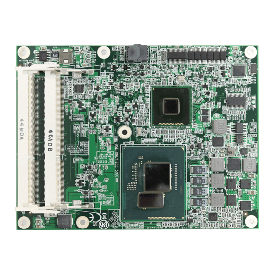
Introduction 1.1 The Product The EmETXe-i87M2 Series is a space-conscious CPU board of 125 mm x 95 mm to take up only small footprint in your system. By the architecture of Type 6, the board has two high-performance connectors to promise stable data passing rate. -
Page 11: Specifications
Introduction 1.3 Specifications System ® Soldered onboard 5 Generation Intel Core™ i7-5700EQ 2.0GHz 2 x DDR3L ECC SO-DIMM sockets, supporting 1600MHz up to Memory 16GB SDRAM Chipset Intel PCH QM87 ® BIOS UEFI BIOS ® Watchdog Timer 1~255 levels reset 12 x USB ports: USB Port - 8 x USB 2.0 ports... -
Page 12: Inside The Package
1.4 Inside the Package Before you begin installing your single board, please make sure that the following materials have been shipped: 1 x EmETXe-i87M2 COM Express CPU Module 1 x Driver CD 1 x Quick Installation Guide If any of the above items is damaged or missing, contact your vendor immediately. -
Page 13: Optional Accessories
Find the drivers on CD by the following paths: Windows 7 Driver Path Chipset \EmETXe-i87M2\Chipset\Chipset_10.1.1.7 32bit: \EmETXe-i87M2\Graphic\32bit\Intel® Graphics Driver Production Version 15.40.8.4281 Graphic 64bit: \EmETXe-i87M2\Graphic\64bit\Intel® Graphics Driver Production Version 15.40.8.64.4281 32bit: \EmETXe-i87M2\Audio\32bit Audio... - Page 14 Board Overview Windows 8.1 Driver Path Chipset \EmETXe-i87M2\Chipset\Chipset_10.1.1.7 32bit: \EmETXe-i87M2\Graphic\32bit\Intel® Graphics Driver Production Version 15.40.8.4281 Graphic 64bit: \EmETXe-i87M2\Graphic\64bit\Intel® Graphics Driver Production Version 15.40.8.64.4281 32bit: \EmETXe-i87M2\Audio\32bit Audio 64bit: \EmETXe-i87M2\Audio\64bit Ethernet \EmETXe-i87M2\Ethernet\20_0_CD \EmETXe-i87M2\ME\ME9.0_5M_V9.0.13.1402 - 6 -...
-
Page 15: Chapter 2 - Board Overview
Board Overview Chapter 2 Board Overview - 7 -... -
Page 16: What Is "Com Express
Module Type 1 and 10 support single connector with two rows (220 pins). Module Type 2, 3, 4, 5 and 6 support two connectors with four rows (440 pins). EmETXe-i87M2 Series is a Type-6 module. Difference between Standard Type 6 and EmETXe-i87M2 Series is listed as below: Module Type... -
Page 17: Board Dimensions
Board Overview 2.2 Board Dimensions The following illustration shows the dimension of EmETXe-i87M2 Series, with the measurements in width, depth, and height called out. 70.64 55.68 79.53 COM Express CD Connector COM Express AB Connector 45.35 Unit: mm Ø2.6*Ø6.5 - 9 -... -
Page 18: Block Diagram
Board Overview 2.3 Block Diagram 1 x PCIex16 (Gen3) DDR3L W/ ECC-1600MT/s 2 x ECC SO-DIMM DDR3L sockets Soldered DDI3 (DP) onboard Gen Intel ® DDI2 (DVI) Core Processor (Broadwell-H) PTN3460 Dual Chnnels DDI1 (DP) DDI1 eDP to LVDS 24-bit LVDS (Alternative, Default) (eDP) transmitter... -
Page 19: Connector Pin Definition
Board Overview 2.4 Connector Pin Definition Being a most commonly-used Type 6, the EmETXe-i87M2 Series features two board-to-board connectors on bottom side. Top Side BE BD BE BD 9 8 7 6 5 4 3 2 1 9 8 7 6... - Page 20 Board Overview COM Express AB Connector (bottom side) B1 GND (FIXED) GND (FIXED) PCIE_RX4- PCIE_TX4- B2 GBE0_ACT# GBE0_MDI3- GPO2 B3 LPC_FRAME# GBE0_MDI3+ PCIE_RX3+ PCIE_TX3+ B4 LPC_AD0 GBE0_LINK100# PCIE_RX3- PCIE_TX3- B5 LPC_AD1 GBE0_LINK1000# B6 LPC_AD2 GBE0_MDI2- PCIE_RX2+ PCIE_TX2+ B7 LPC_AD3 GBE0_MDI2+ PCIE_RX2- PCIE_TX2- B8 LPC_DRQ0#...
- Page 21 Board Overview COM Express CD Connector (bottom side) PEG_TX1- PEG_RX1- GND (FIXED) GND (FIXED) TYPE2# TYPE1# USB_SSTX0- USB_SSRX0- PEG_TX2+ PEG_RX2+ USB_SSTX0+ USB_SSRX0+ PEG_TX2- PEG_RX2- GND (FIXED) GND (FIXED) USB_SSTX1- USB_SSRX1- PEG_TX3+ PEG_RX3+ USB_SSTX1+ USB_SSRX1+ PEG_TX3- PEG_RX3- RSVD RSVD USB_SSTX2- USB_SSRX2- RSVD RSVD USB_SSTX2+...
- Page 22 This page is intentionally left blank. - 14 -...
-
Page 23: Chapter 3 - Installation & Maintenance
Installation & Maintenance Chapter 3 Installation & Maintenance - 15 -... -
Page 24: Installing The Cpu Module On Carrier Board
1. Find the COM Express connectors on carrier board PBE-1702, which is available in Section 1.5.1 Optional Accessories on page 2. Embed EmETXe-i87M2 Series into PBE-1702 via COM Express connectors as below; that is, COM Express AB to AB and CD to CD. - 16 -... -
Page 25: Installing The Heatsink
Installation & Maintenance 3.2 Installing the Heatsink 1. Locate EmETXe-i87M2 Series mounted on PBE-1702. 2. Prepare the heatspred included in optional accessories. (See Section 1.5.1 Optional Accessories on page 5) Put heatspred on the CPU module and lock it. Make sure thermal grease in contact with CPU and chipset on CPU module. - Page 26 This page is intentionally left blank. - 18 -...
-
Page 27: Chapter 4 - Bios
BIOS Chapter 4 BIOS - 19 -... -
Page 28: Main
Aptio Setup Utility - Copyright (C) 2015 American Megatrends, Inc. Main Advanced Chipset Security Boot Save & Exit BIOS Information Choose the system default Project Version EmETXe-i87M2 language. BIOS Version 1.00 Build Date and Time 12/10/2015 16:47:23 System Language [English] System Date... - Page 29 BIOS Set the system time. Use Tab to switch between Time elements. System Time The time format is: Hour: 00 to 23 ► Minute: 00 to 59 Second: 00 to 59 Key Commands BIOS Setup Utility is mainly a key-based navigation interface. Please refer to the following key command instructions for navigation process.
-
Page 30: Advanced
BIOS 4.2 Advanced The “Advanced” setting page provides you the options to configure the details of your hardware, such as ACPI, CPU, SATA, AMT, USB and Super IO. Aptio Setup Utility - Copyright (C) 2015 American Megatrends, Inc. Main Chipset Security Boot Save &... - Page 31 BIOS CSM Configuration See Section 4.2.9 CSM Configuration on page 30 USB Configuration See Section 4.2.10 USB Configuration on page 31 Intel(R) Ethernet See Section 4.2.11 Intel(R) Ethernet Connection I218-LM Connection I218-LM on page 33 - 23 -...
-
Page 32: Cpu Configuration
BIOS 4.2.1 CPU Configuration Setting Description Enabled (default) for Windows XP and Linux (OS opti- mized for Hyper-Threading Technology) and Disabled Hyper-threading for other OS (OS not optimized or Hyper-Threading Technology). When Disabled only one thread per en- abled core is enabled. Number of cores to enable in each processor pack- Active Processor age. -
Page 33: Trusted Computing
BIOS 4.2.2 Trusted Computing Access this submenu to enable/disable the Trusted Computing function. Setting Description Security Device Enable/Disable (default) the TPM Support Support TPM State Enable (default) /disable Security Device Set the supported device Device Select Options: Auto (default), TPM1.2 or TPM 2.0. ►... -
Page 34: Super Io Configuration
BIOS 4.2.5 Super IO Configuration Setting Description Serial Port 1 Configuration Serial Port 2 Configuration See below Parallel Port Configuration Sets whether the system should power on or power off when the power resumes after ac- Restore AC Power loss cidental power loss. -
Page 35: Hardware Monitor
BIOS Parallel Port Configuration Setting Description Parallel Port Enable (default)/Disable Parallel Port (LPT/LPTE). Select an optimal setting for Super IO device. Options: Auto(default); -- IO=378h; IRQ5 ► Change Settings -- IO=378h; IRQ3, 4, 5, 6, 7, 10, 11, 12 -- IO=3BCh; IRQ3, 4, 5, 6, 7, 10, 11, 12 -- IO=378h -- IO=278h -- IO=3BCh. -
Page 36: S5 Rtc Wake Settings
BIOS 4.2.7 S5 RTC Wake Settings Access this submenu to enable/disable the system to wake up on a specified time. The featured setting is: Setting Description Sets if to awake the system at a defined moment. Options available are Enabled and Disabled (default). Enable this feature to awake the system at a defined moment in time. -
Page 37: Sata Configuration
BIOS 4.2.8 SATA Configuration Aptio Setup Utility - Copyright (C) 2015 American Megatrends, Inc. Advanced SATA Controller(s) [Enabled] Console Redirection Enable or SATA Mode Selection [AHCI] Disable. SATA Controller Speed [Default] Serial ATA Port 0 Empty Software Preserve Unknown Port 0 [Enabled] Hot Plug [Disabled]... -
Page 38: Csm Configuration
BIOS Identify the SATA port is connected to Solid State SATA Device Type Drive or Hard Disk Drive (default). On an edge detect from 0 to 1, the PCH starts a Spin Up Device COMRESET initialization sequence to the device. Options: Enabled or Disabled (default) ►... -
Page 39: Usb Configuration
BIOS 4.2.10 USB Configuration Setting Description Enables (default) Legacy USB support. AUTO op- tion disables legacy support if no USB devices are Legacy USB Support connected. DISABLE option will keep USB devices available only for EFI applications. Enable (default)/Disable USB3.0 (XHCI) Controller USB3.0 Support support. - Page 40 BIOS This is a submenu to configure the features of USB hardware delay and time-out. The featured settings are: Setting Description Use this item to set the time-out value for control, bulk, and interrupt trans- USB Transfer fers. time-out Options available are: 1 sec, 5 sec, 10 sec, 20 sec Use this item to set USB mass storage Device reset...
-
Page 41: Intel(R) Ethernet Connection I218-Lm
BIOS 4.2.11 Intel(R) Ethernet Connection I218-LM Setting Description NIC Configuration See next page. Blink LEDs (range 0-15 Blink LEDs for the specified duration (up to 15 seconds) seconds). Link Status Link Status NIC Configuration Setting Description Change link speed and duplex for current port. Link Speed Options: AutoNeg (default), 10 Mbps Half, 10 Mbps ►... -
Page 42: Chipset
BIOS 4.3 Chipset Aptio Setup Utility - Copyright (C) 2015 American Megatrends, Inc. Main Advanced Chipset Security Boot Save & Exit System Agent (SA) Configuration Check to enable VT-d function VT-d [Enabled] on MCH. Above 4GB MMIO BIOS assigment [Disabled] Display Control Memory Configuration PCH-IO Configuration... -
Page 43: Display Control
BIOS 4.3.1 Display Control Aptio Setup Utility - Copyright (C) 2015 American Megatrends, Inc. Chipset Select the Video Display Control Device which will be activated during POST. Boot Display [VBIOS Default] This has no effect if Active LFP [Disabled] external graphics present. -
Page 44: Memory Configuration
BIOS 4.3.2 Memory Configuration Aptio Setup Utility - Copyright (C) 2015 American Megatrends, Inc. Chipset Memory Information Memory RC Version 2.7.1.0 Memory Frequency 1600 Mhz Total Memory 8192 MB (DDR3) Memory Voltage 1.35v DIMM#1 8192 MB (DDR3) DIMM#2 Not Present CAS Latency (tCL) Minimum delay time CAS to RAS (tRCDmin) -
Page 45: Sb Pcie Configuration
BIOS 4.3.3 SB PCIe Configuration Aptio Setup Utility - Copyright (C) 2015 American Megatrends, Inc. Chipset PCI Express x1 Slot 1 SB PCIe Configuration Settings. PCI Express x1 Slot 1 PCI Express x1 Slot 1 PCI Express x4 Slot →←: Select Screen ↓↑: Select Item Enter: Select +/-: Change Opt. -
Page 46: Usb Configuration
BIOS 4.3.4 USB Configuration Aptio Setup Utility - Copyright (C) 2015 American Megatrends, Inc. Chipset USB Configuration Mode of operation of xHCI controller. Auto - Enable the XHCI Mode [Enabled] xHCI controller and reroute PCH LAN Controller [Enabled] USB ports via the _OSC ACPI method call. -
Page 47: Hdac Configuration
BIOS 4.3.5 HDAC Configuration Aptio Setup Utility - Copyright (C) 2015 American Megatrends, Inc. Chipset Control Detection of the Azalia HDAC Configuration device. Azalia [Enabled] Disabled = Azalia will be unconditionally disabled Enabled = Azalia will be unconditionally Enabled Auto = Azalia will be enabled if present, disabled otherwise. -
Page 48: Lan Configuration
BIOS 4.3.6 LAN Configuration Aptio Setup Utility - Copyright (C) 2015 American Megatrends, Inc. Chipset Select the Video LAN Configuration Device which will be activated during POST. PCH LAN Controller [Enabled] This has no effect if Wake on LAN [Enabled] external graphics present. -
Page 49: Boot
BIOS 4.4 Boot Aptio Setup Utility - Copyright (C) 2015 American Megatrends, Inc. Main Advanced Chipset Boot Security Save & Exit Boot Configuration Number of seconds to wait for Bootup NumLock State [On] setup activation key. 65535 (0xFFFF) means indefinite Quiet Boot [Disabled] waiting. -
Page 50: Security
BIOS 4.5 Security The Security menu sets up the administrator password. Aptio Setup Utility - Copyright (C) 2015 American Megatrends, Inc. Main Advanced Chipset Security Boot Save & Exit Password Description Set Adminstrator Password Minimum length Maximum length Administrator Password →←: Select Screen : Select Item Enter: Select... -
Page 51: Save & Exit
BIOS 4.6 Save & Exit Aptio Setup Utility - Copyright (C) 2015 American Megatrends, Inc. Main Advanced Chipset Boot Security Save & Exit Save Changes and Exit Exit system setup after saving Discard Changes and Exit the changes. Save Changes and Reset Discard Changes and Reset Restore Defaults launch EFI Shell from filesystem device... - Page 52 This page is intentionally left blank. - 44 -...
- Page 53 Appendix Appendix - 45 -...
-
Page 54: Appendix A: I/O Port Address Map
Appendix Appendix A: I/O Port Address Map Each peripheral device in the system is assigned a set of I/O port addresses which also becomes the identity of the device. The following table lists the I/O port addresses used. Address Device Description 0x000003F8-0x000003FF Communications Port (COM1) 0x000002F8-0x000002FF... - Page 55 Appendix 0x00001854-0x00001857 Motherboard resources 0x000000F0-0x000000F0 Numeric data processor 0x00000000-0x0000001F PCI bus 0x00000D00-0x0000FFFF PCI bus 0x000030E0-0x000030E7 PCI Serial Port 0x00000378-0x0000037F Printer Port (LPT1) 0x00000020-0x00000021 Programmable interrupt controller 0x00000024-0x00000025 Programmable interrupt controller 0x00000028-0x00000029 Programmable interrupt controller 0x0000002C-0x0000002D Programmable interrupt controller 0x00000030-0x00000031 Programmable interrupt controller 0x00000034-0x00000035 Programmable interrupt controller 0x00000038-0x00000039...
-
Page 56: Appendix B: Bios Memory Mapping
Appendix 0x000003C0-0x000003DF Standard VGA Graphics Adapter 0x00000070-0x00000077 System CMOS/real time clock 0x00000040-0x00000043 System timer 0x00000050-0x00000053 System timer Appendix B: BIOS Memory Mapping Address Device Description 0xB2000000-0xB201FFFF Ethernet Controller 0xB203C000-0xB203CFFF Ethernet Controller 0xB2034000-0xB2037FFF High Definition Audio Controller 0xB2030000-0xB2033FFF High Definition Audio Controller 0xFED00000-0xFED003FF High precision event timer 0xFF000000-0xFFFFFFFF... -
Page 57: Appendix C: Interrupt Request Lines (Irq)
Appendix 0xB2039000-0xB20397FF Standard AHCI 1.0 Serial ATA Controller Standard Enhanced PCI to USB Host Con- 0xB203B000-0xB203B3FF troller Standard Enhanced PCI to USB Host Con- 0xB203A000-0xB203A3FF troller 0xA0000-0xBFFFF Standard VGA Graphics Adapter 0xB1000000-0xB1FFFFFF Standard VGA Graphics Adapter 0xC0000000-0xCFFFFFFF Standard VGA Graphics Adapter 0xFED40000-0xFED44FFF Trusted Platform Module 1.2 0xB2020000-0xB202FFFF... -
Page 58: Appendix D: Watchdog Timer (Wdt) Setting
Appendix Appendix D: Watchdog Timer (WDT) Setting WDT is widely used for industry application to monitor the activity of CPU. Ap- plication software depends on its requirement to trigger WDT with adequate timer setting. Before WDT time out, the functional normal system will reload the WDT. - Page 59 Appendix delay(DELAY_TIME); /* Watchdog Timer Control Register */ SMB_Byte_WRITE(SMB_PORT_AD,SMB_DEVICE_ADD,0x36,0x72); int WDT_Count(void) int iData; /* Watchdog Timer Range Register */ iData = SMB_Byte_READ(SMB_PORT_AD,SMB_DEVICE_ADD,0x37); return iData; void WDT_Clear(int iCount) /* Watchdog Timer Range Register */ SMB_Byte_WRITE(SMB_PORT_AD,SMB_DEVICE_ADD,0x37,iCount); void WDT_Stop(void) /* Watchdog Timer Control Register */ SMB_Byte_WRITE(SMB_PORT_AD,SMB_DEVICE_ADD,0x36,0x52); - 51 -...
Need help?
Do you have a question about the EmETXe-i87M2 and is the answer not in the manual?
Questions and answers