
Related Manuals for Arbor Technology EmETXe-a10R0


Summary of Contents for Arbor Technology EmETXe-a10R0
- Page 1 EmETXe-a10R0 COM Express Compact ® Type 6 CPU Module User’s Manual Version 1.0 2020.12...
- Page 2 Revision History Version Date Description 2020.12 Initial release...
-
Page 3: Table Of Contents
Contents Table of Contents Preface Copyright Notice ..............iii Declaration of Conformity ............ iii CE ..................iii FCC Class B ................iii RoHS ..................iv SVHC / REACH ..............iv Warning ................v Replacing the Lithium Battery ..........v Technical Support ..............v Warranty ................ - Page 4 Content 4.1 Main ................20 4.2 Advanced ..............22 4.2.12 Serial Port Redirection..........22 4.2.13 S5 RTC Wake Settings ..........22 4.3 Chipset ..............22 4.3.1 SB USB Config ............22 4.3.2 PCI-E Port ..............22 4.3.3 Display Configuration ..........22 4.5 Security ................22 4.6 Boot ................22 4.6 Save & Exit ..............22 4.2.1 CPU Configuration ............24 4.2.2 AMD fTPM Configuration ..........25 4.2.3 PCI Subsystem Settings ..........26...
-
Page 5: Preface
Preface Copyright Notice All Rights Reserved. The information in this document is subject to change without prior notice in order to improve the reliability, design and function. It does not represent a commitment on the part of the manufacturer. Under no circumstances will the manufacturer be liable for any direct, indirect, special, incidental, or consequential damages arising from the use or inability to use the product or documentation, even if advised of the possibility of such damages. -
Page 6: Rohs
RoHS ARBOR Technology Corp. certifies that all components in its products are in compliance and conform to the European Union’s Restriction of Use of Haz- ardous Substances in Electrical and Electronic Equipment (RoHS) Directive 2002/95/EC. -
Page 7: Warning
Preface Warning Single Board Computers and their components contain very delicate Integrated Circuits (IC). To protect the Single Board Computer and its components against damage from static electricity, you should always follow the following precautions when handling it : 1. Disconnect your Single Board Computer from the power source when you want to work on the inside. -
Page 8: Warranty
Preface Warranty This product is warranted to be in good working order for a period of two years from the date of purchase. Should this product fail to be in good working order at any time during this period, we will, at our option, replace or repair it at no additional charge except as set forth in the following terms. -
Page 9: Chapter 1 Introduction
Introduction Chapter 1 Introduction - 1 -... -
Page 10: The Product
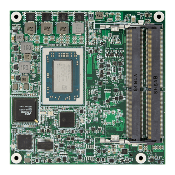
Introduction 1.1 The Product The EmETXe-a10R0 is a space-conscious CPU board of 95 mm x 95 mm to take up only small footprint in your system. By the architecture of Type 6, the board has two high-performance connectors to promise stable data passing rate. -
Page 11: Specifications
Introduction 1.3 Specifications System Soldered onboard AMD Ryzen R1000 R1606G 2.6GHz(Base)/ 3.5GHz (Turbo) or R1505G 2.4GHz(Base)/ 3.3GHz (Turbo) processor 2 x DDR4 ECC SO-DIMM sockets, supporting up Memory to 32GB SDRAM BIOS AMI UEFI BIOS Watchdog Timer 1~255 levels reset USB Port 10 x USB ports: - 8 x USB 2.0 ports... -
Page 12: Inside The Package
Before you begin installing your single board, please make sure that the following materials have been shipped: 1 x EmETXe-a10R0 COM Express CPU Module 1 x Quick Installation Guide If any of the above items is damaged or missing, contact your vendor immediately. -
Page 13: Optional Accessories
1 x SATA cable 2 x COM Flat cables 1.6 Driver(7.2A) Installation To install the drivers, please visit our website at www.arbor.technology. com and download the driver pack from the product page. Driver Path Audio \EmETXe-a10R0\Audio\Win10_Win8.1_Win8_Win7_WHQLx64 Chipset \EmETXe-a10R0\SOC\19.30.01.36.190821a-346304C-AES \EmETXe-a10R0\LAN - 5 -... - Page 14 This page is intentionally left blank. - 6 -...
-
Page 15: Chapter 2 - Board Overview
Board Overview Chapter 2 Board Overview - 7 -... -
Page 16: What Is "Com Express
Module Type 2, 3, 4, 5 and 6 support two connectors with four rows of pins (440 pins) Connector placement and most mounting holes have transparency between Form Factors. The differences among the Module Type 6 and EmETXe-a10R0 are summarized in table below: Module Type... -
Page 17: Board Dimensions
Board Overview 2.2 Board Dimensions φ 2,7* φ 6.0 54,48 32,39 Unit:mm - 9 -... -
Page 18: Block Diagram
Board Overview 2.3 Block Diagram SODIMM1, 2 DDR4-2400MT/s DDI0 (DP, BOM optional, w/o LVDS) DDR4 SO-DIMM Support ECC sockets DDI0 (DP) Dual Chnnels CH7511B DDI1 24-bit LVDS DP to LVDS Intel i210IT GbE controller 1 x PCIex1 2 x PCIex1 lanes 1 x PCIex1 Gen3 PEC8606... -
Page 19: Connector Pin Definition
Board Overview 2.4 Connector Pin Definition Being a most commonly-used Type 6, the EmETXe-a10R0 features two board- to-board connectors on bottom side. Top Side Bottom Side COM Express AB Connector COM Express CD Connector Unit: mm - 11 -... - Page 20 Board Overview COM Express AB Connector (bottom side) GND(FIXED) A1 GND(FIXED) PCIE_RX4- PCIE_TX4- GBE0_MDI3- A2 GBE0_ACT# GBE0_MDI3+ A3 LPC_FRAME# GBE0_LINK100# A4 LPC_AD0 GBE0_LINK1000# A5 LPC_AD1 GND(FIXED) GND(FIXED) GBE0_MDI2- A6 LPC_AD2 GBE0_MDI2+ A7 LPC_AD3 N/C A8 LPC_DRQ0# GPO3 GPI1 GBE0_MDI1- A9 LPC_DRQ1# PCIE_RX1+ PCIE_TX1+...
- Page 21 Board Overview COM Express CD Connector (bottom side) GND(FIXED) GND(FIXED) PEG_TX1- PEG_RX1- TYPE2# USB_SSTX0- USB_SSRX0- PEG_TX2+ PEG_RX2+ USB_SSTX0+ USB_SSRX0+ PEG_TX2- PEG_RX2- GND(FIXED) GND(FIXED) USB_SSTX1- USB_SSRX1- PCIE_TX3+ PCIE_RX3+ USB_SSTX1+ USB_SSRX1+ PCIE_TX3- PCIE_RX3- RSVD RSVD RSVD RSVD GND(FIXED) GND(FIXED) RSVD RSVD DDI1_CTRLCLK_AUX+ GND(FIXED) GND(FIXED) DDI1_CTRLCLK_AUX-...
- Page 22 This page is intentionally left blank. - 14 -...
-
Page 23: Chapter 3 - Installation & Maintenance
Installation & Maintenance Chapter 3 Installation & Maintenance - 15 -... -
Page 24: Installing The Cpu Module To Carrier Board
Installation & Maintenance 3.1 Installing the CPU Module to Carrier Board 1. Find the heat sink included in optional accessories. (See section 1.5.1 Optional Accessories on page 5) Apply thermal grease to be in contact with CPU and chipset on CPU module. 2. - Page 25 3. Find the COM Express connectors on carrier board PBE-1705, which is available in Section 1.5.1 Optional Accessories on page 4. Mount the EmETXe-a10R0 into PBE-1705 via COM Express connectors as below; that is, COM Express AB to AB and CD to CD. CD connector AB connector 5.
- Page 26 This page is intentionally left blank. - 18 -...
-
Page 27: Chapter 4 - Bios
BIOS Chapter 4 BIOS - 19 -... -
Page 28: Main
BIOS 4.1 Main The Aptio BIOS provides a Setup utility program for specifying the system configurations and settings. The BIOS RAM of the system stores the Setup utility and configurations. When you turn on the computer, the AMI BIOS is immediately activated. - Page 29 BIOS System Time Sets system time. Key Commands BIOS Setup Utility is mainly a key-based navigation interface. Please refer to the following key command instructions for navigation process. Keystroke Function Move to highlight a particular configuration screen from ◄ ► the top menu bar / Move to highlight items on the screen ▼...
-
Page 30: Advanced
BIOS 4.2 Advanced Setting Description CPU Configuration 4.2.1 CPU Configuration on page 24 AMD fTPM Configuration See 4.2.2 AMD fTPM Configuration on page 25 PCI Subsystem Settings See 4.2.3 PCI Subsystem Settings on page 26 ACPI Settings 4.2.4 ACPI Settings on page 27 Trusted Computing 4.2.5 Trusted Computing on page 28 NVMe Configuration... - Page 31 BIOS Network Stack 4.2.11 Network Stack Configuration on page Configuration AMD CBS 4.2.12 AMD CBS on page 36 - 23 -...
-
Page 32: Cpu Configuration
BIOS 4.2.1 CPU Configuration Setting Description Enable (default) / Disable No-execute page protection NX Mode Function. Enable (default) / Disable CPU Virtualization. SVM Mode - 24 -... -
Page 33: Amd Ftpm Configuration
BIOS 4.2.2 AMD fTPM Configuration Setting Description To select AMD fTPM switch. Options: AMD CPU fTPM (default): Depend on Tcg mod- ► AMD fTPM Switch ule) Route to LPC TPM ► Enable(default) ► Erase fTPM NV for factory rest when a Erase fTPM NV new CPU is installed. -
Page 34: Pci Subsystem Settings
BIOS 4.2.3 PCI Subsystem Settings Setting Description Value to be programmed into PCI Latency timer Register. PCI Latency Timer Default: 32 PCI Bus Clocks ► PCI-X Latency Value to be programmed into PCI Latency timer Register. Timer Default: 64 PCI Bus Clocks ►... -
Page 35: Acpi Settings
BIOS 4.2.4 ACPI Settings Setting Description Enables (default) or Disables System ability to Hibernate Enable Hibernation (OS/S4 Sleep State). This option may be not effective with some OS. Select ACPI sleep state the system will enter when the SUSPEND button is pressed. ACPI Sleep State Options: Suspend Disabled, S3 (Suspend to ►... -
Page 36: Trusted Computing
BIOS 4.2.5 Trusted Computing Setting Description Enable (default) or Disable BIOS support for security Security Device device. O.S. will not show Security Device. TCG EFI Support protocol and INT1A interface will not be available. Select the TPM device: Options: TPM 1.2, TPM 2.0 and Auto (default) ►... -
Page 37: Nvme Configuration
BIOS 4.2.6 NVMe Configuration Access this submenu to view the NVMe controller and driver information. - 29 -... -
Page 38: Super Io Configuration
BIOS 4.2.7 Super IO Configuration Setting Description Serial Port 1/2/3/4 & Par- See next page. allel Port Configuration Specify what state to go to when power is re-applied after a power failure. Restore AC Power Loss Options: Last State, Power On and ►... -
Page 39: Hardware Monitor
BIOS 4.2.8 Hardware Monitor Access this page to view the hardware information. - 31 -... -
Page 40: Csm Configuration
BIOS 4.2.9 CSM Configuration Setting Description CSM Support Enable (default) or Disable CSM Support. Control the Legacy/UEFI ROMs priority. Boot option filter Options: UEFI and Legacy (default), Legacy only ► and UEFI only Control the execution of UEFI and Legacy PXE OpROM Network Options: Do not lauch (default), UEFI and Legacy ►... -
Page 41: Usb Configuration
BIOS 4.2.10 USB Configuration Select this submenu to view the status of the USB ports and configure USB features. Setting Description Sets legacy USB support. Options: Enabled (default), Disabled and Auto. ► Legacy USB AUTO option disables legacy support if no USB Support devices are connected. - Page 42 BIOS USB hardware delay and time-out Use this item to set the time-out value for control, bulk, USB Transfer time- and interrupt transfers. Options available are: 1 sec, 5 sec, 10 sec, 20 sec ► (default) Use this item to set USB mass storage device start unit Device reset time- command time-out.
-
Page 43: Network Stack Configuration
BIOS 4.2.11 Network Stack Configuration Setting Description Enables/disables UEFI network stack. Network Stack Disabled is the default. ► - 35 -... -
Page 44: Amd Cbs
BIOS 4.2.12 AMD CBS Setting Description Downcore control Set the the number of cores to be used. SMTEN Can be used to disable multithreading. Core Performance To dynamically adjust and control the processor oper- Boost ating frequency Gloabl C-Sate Control Global C-state Enables or Disables (default) IO based C-stat genera- Control... -
Page 45: Chipset
BIOS 4.3 Chipset Setting Description SB USB Configuratoin 4.3.1 SB USB Config on page 38 PCI-E Port 4.3.2 PCI-E Port on page 39 Display Configuration 4.3.3 Display Configuration on page 40 - 37 -... -
Page 46: Sb Usb Config
BIOS 4.3.1 SB USB Config Setting Description XHCI0 Port 0~5 Enable (default) /disable (default) xHCI0 port 0~5. - 38 -... -
Page 47: Pci-E Port
BIOS 4.3.2 PCI-E Port Setting Description PCIe Port Con- Enable (default) or disable the PCIe port. trol Device 1 Select Device 1 function. Fun1~7 Options: Auto (default), Disabled, and Enabled ► Disable or set the ASPM level. Force L0s will force all inks to L0s state. -
Page 48: Display Configuration
BIOS 4.3.3 Display Configuration Item Description Active LVDS Enable or Disable (\default) active LVDS control. - 40 -... -
Page 49: Security
BIOS 4.4 Security The Security menu sets up the administrator password. Setting Description To set up an administrator password: 1. Select Administrator Password. The screen then pops up an Create New Password Administrator dialog. Password 2. Enter your desired password that is no less than 3 char- acters and no more than 20 characters. -
Page 50: Boot
BIOS 4.5 Boot Setting Description Select the keyboard NumLock state. Boot NumLock State Options: On and Off (default). ► Quiet Boot Enable or Disable (default) Quiet Boot option. Enable or Disable (default) boot with initializa- tion of a minimal set of devices required to launch Fast Boot active boot option. -
Page 51: Save & Exit
BIOS 4.6 Save & Exit Setting Description Exit system setup after saving the changes. Save Changes and Enter the item and then a dialog box pops up: ► Exit Save configuration and exit? (Yes/ No) Exit system setup without saving the changes. Discard Changes and Enter the item and then a dialog box pops up: ►... - Page 52 This page is intentionally left blank. - 44 -...
-
Page 53: Appendix
Appendix Appendix - 45 -... -
Page 54: Appendix A: Watchdog Timer (Wdt) Setting
Appendix Appendix A: Watchdog Timer (WDT) Setting WDT is widely used for industry application to monitor the activity of CPU. Ap- plication software depends on its requirement to trigger WDT with adequate timer setting. Before WDT time out, the functional normal system will reload the WDT. - Page 55 Appendix outportb(sioIndex, 0xF0); /* Enable WDTRST# Output */ outportb(sioData, 0x80); iWDTCount = iCount; outportb(sioIndex, 0xF6); /* Set WDT Timeout value */ outportb(sioData, iCount); outportb(sioIndex, 0xF5); /* Set Configure and Enable WDT timer, Start countdown */ outportb(sioData, 0x32); outportb(sioIndex, 0xAA); /* Disable Super I/O */ void WDT_Stop(void) outportb(sioIndex, 0x87);...
- Page 56 Appendix outportb(sioIndex, 0xAA); /* SIO - Disable */ return iData; - 48 -...
-
Page 57: Appendix B: Dio Sample Code
Appendix Appendix B: DIO Sample Code /*---------------------------------------------------------------------------*/ #include “math.h” #include “stdio.h” #include “dos.h” /* SM Bus */ int SMB_PORT_AD = 0xB00; int SMB_DEVICE_ADD = 0x40; /* TCA6408A’s Add = 6eh or 9ch */ int main(void) int iInput; GPIOMode(0xF0); delay(10000); GPIOData(0x0A); delay(30000);...
Need help?
Do you have a question about the EmETXe-a10R0 and is the answer not in the manual?
Questions and answers