
Related Manuals for Mile Marker H9000


Summary of Contents for Mile Marker H9000
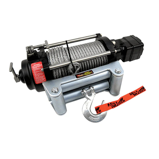
- Page 1 Installation & Operator’s Manual H9000 70-50080C H10500 70-50050C H12000 70-52000C...
-
Page 2: Table Of Contents
TABLE OF CONTENTS Safety Warnings ..........2 Precautions ............3 Getting Started ..........4 Attaching Valve Assembly ........5 Wiring Instructions ..........6 Plumbing Connections ........7 Winch Operation ..........8 2 Speed Lever Positions ........9 Winching Tips & Techniques ......10 Accessories Parts Breakdown .......12 34 Kit Application Guide.........13 Warranty ............14 PAGE 1 2121 Blount Road Pompano Beach, FL 33069... -
Page 3: Safety Warnings
SAFETY WARNINGS LEARN TO USE YOUR MILE MARKER WINCH: After winch has been installed, take some time and practice using it so you will be familiar with ALL OPERATIONS. Periodically check the winch installation to ensure that all bolts are tight. To ensure proper operation, carefully inspect for any damaged parts before operating the winch. -
Page 4: Precautions
PRECAUTIONS Keeps hands and body away from roller fairlead (cable intake slot) when operating. Secure vehicle in position before using winch. Do not exceed winch load weight capacity. Be certain winch is properly bolted to a structure (or vehicle) that can hold the winch load. Always use proper couplings when connecting winch cable hook to load. -
Page 5: Getting Started
This may allow the winch to be mounted easier on some winch mounts or for other applications. The motor on Mile Marker 2 speed winches may also be rotated in 90º increments if needed. This may allow easier installation on some winch mounts. -
Page 6: Attaching Valve Assembly
ATTACHING VALVE ASSEMBLY The Mile Marker solenoid valve should be mounted away from any areas where heat may be considered too extreme such as an exhaust manifold or turbo. Be sure all plumbing and wiring reaches from the area selected without being stressed. The solenoid valve should be mounted by using the bracket and alien screws supplied. -
Page 7: Wiring Instructions
WIRING INSTRUCTIONS Electrical Connections The valving system is designed to default to the power steering gearbox so power steering is always available even when the winch is in use. The power source to the solenoid is not energized until the four pole quick connector plug is plugged in. Each solenoid has two black wires, either of which can be used as a ground or for electric power. -
Page 8: Plumbing Connections
PLUMBING CONNECTIONS (Refer to previous page) Keep all hoses away from any areas where heat may be considered too extreme (such as exhaust manifold or turbo). Lines should not to be allowed to rub on any abrasive or vibrating surfaces. In some applications, 90° fittings on the solenoid valve are necessary to make hose mounting more flexible. -
Page 9: Winch Operation
WINCH OPERATION General The vehicle’s steering pump is used to power the winch. The engine must be running while operating the winch, as the engine turns the power steering pump which pumps fluid to rotate the winch. The winch will have full pulling capabilities at an engine idle. The winch is operated by an electric activated switching valve. -
Page 10: Speed Lever Positions
2 SPEED LEVER POSITIONS VIEW #1 VIEW #2 FREE LEVER #1 LEVER #1 FREE HIGH FREE FREE LEVER #2 LOCK SPOOL LEVER #2 FREE HIGH WARNING DO NOT MOVE SHIFT LEVERS WITH LOAD ON WINCH CABLE VIEW #3 VIEW #4 LEVER #1 LEVER #1 FREE... -
Page 11: Winching Tips & Techniques
Safety Tips • DO NOT DISENGAGE CLUTCH LEVER WHEN THERE IS A LOAD ON THE WINCH. Mile Marker electric winches utilize an automatic load holding brake, therefore no adjustment to clutch is needed to maintain load. - Page 12 The cable should be replaced immediately if any sign of burrs or broken strands are evident. A frayed cable with broken strands should be replaced immediately. Always replace the cable with a Mile Marker recommended replacement part. Any substitution must be identical in strength, quality, lay and stranding.
-
Page 13: Accessories Parts Breakdown
ACCESSORIES PARTS BREAKDOWN Listing Description HYDRAULIC BOX W/ IP67 CONNECTOR PUMP ADAPTER GEARBOX ADAPTER JOYSTICK REMOTE WITH P67 CONNECTOR 4 HYDRAULIC HOSE ASSEMBLIES 90 DEG 10 MORB - 6 MJIC MOTOR FITTING WIRING HARNESS KIT 2062-8-6S 90DEG #8 MOB X #6MJIC 3-WAY SOLENOID VALVE/PLACKER KIT MOUNTING BRACKET KIT 202702-8-6S STRAIGHT FITTING FOR 34 SERIES KIT... -
Page 14: Kit Application Guide
34 KIT APPLICATION GUIDE PART NUMBER APPLICATION PART NUMBER APPLICATION AM GENERAL VALVE KIT - '78-'98 FORD FULL SIZE 34-5010-07H (WITH HYDRO BOOST) 34-5010-17 VALVE KIT - H1 (CIVILIAN) VALVE KIT - '83-'92 FORD RANGER, 34-5020-04 '90-'94 EXPLORER CHEVY/GMC/H2 VALVE KIT - '93-'96 FORD RANGER, 34-5020-14 VALVE KIT - '72-'87 GM C/K, '88-'91 RV SERIES 34-5020-05... -
Page 15: Warranty
Mile Marker will, as its option, repair or replace the product or necessary replacement parts at no charge to you, provided you remove the product from the vehicle and return it prepaid to Mile Marker Industries. - Page 16 2121 BLOUNT ROAD POMPANO BEACH, FL 33069 USA 800.886.8647 MILEMARKER.COM INFO@MILEMARKER.COM...
Need help?
Do you have a question about the H9000 and is the answer not in the manual?
Questions and answers