
Related Manuals for SAMES KREMLIN Nanogun Airspray H2O


Summary of Contents for SAMES KREMLIN Nanogun Airspray H2O
- Page 1 User manual Nanogun Airspray GNM 6080 SAMES KREMLIN SAS - 13, Chemin de Malacher - 38240 MEYLAN - FRANCE Tel. 33 (0)4 76 41 60 60 - www.sames-kremlin.com Index revision : B - September 2019 7117...
- Page 2 The descriptions and characteristics contained in this document may be modified without prior notice. © SAMES KREMLIN 2017 WARNING : SAMES KREMLIN SAS has been declared as a training centre with the Ministry of employment. Our company organises training courses providing the indispensable know-how for the installation and maintenance of our equipment all year long.
-
Page 3: Table Of Contents
Nanogun Airspray H GNM 6080 1. Product identification - - - - - - - - - - - - - - - - - - - - - - - - - - - - - - - - - - 5 1.1. - Page 4 10.11. High-voltage cascade ......34 10.12. Barrel ......... . 35 10.13.
-
Page 5: Product Identification
1. Product identification The markings of the Nanogun Airspray H O guns differentiate the configuration of the low pres- sure gun (LP). 1.1. Version identification 1.1.1. On the gun barrel The marking on the barrel is the same across the entire Nanogun Airspray H O range. -
Page 6: Gnm 6080 Control Module
This control step pertains to each of the electrical and electronic components as well as to the set of very specific program(s); you should contact your subsidiary, distributor or regular SAMES KREMLIN representative, who will inform you of the appropriate steps to take. -
Page 7: Health And Safety Guidelines
WARNING : Before using the Nanogun Airspray H O gun, be sure that all operators: • Have previously been trained by the SAMES KREMLIN company, or by its distributors authorised to this effect. • have read and understood the user’s manual as well as all installation and use rules listed below. -
Page 8: Rules Of Use
• The floor where the operator works must be antistatic (either unclad concrete flooring or a metal grating). Never cover the floor with an insulating covering. In potentially explosive locations, the floor assemblies must be antistatic, in accordance with Standard EN 61340- 4-1. -
Page 9: Maintenance Rules
WARNING : Shutting off the compressed air supply line does not prohibit triggering high voltage should the trigger be activated. • The operator must have been trained by a SAMES KREMLIN company or else by the Distributors it has certified for this purpose, in order to carry out the Nanogun Airspray H gun maintenance operations. -
Page 10: Products Used
2.4.1. Products used Given the diversity of products used and the impossibility to inventory the characteristics of these products, SAMES KREMLIN cannot be held liable for: • for any incompatibility in the materials of products used whenever they come into con- tact with the materials listed below: •... -
Page 11: Description Of Spray Gun And Gnm 6080 Control Module
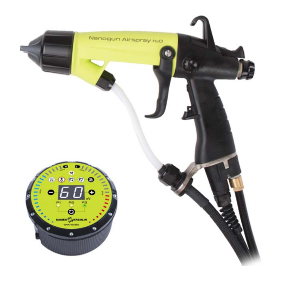
3. Description of spray gun and GNM 6080 control module The Nanogun Airspray H O guns are intended for spray paints or water based water-thinnable or hydrosoluble varnish. Sprayed liquids must be non-flammable (defined in the Standard EN 50059:2018 Annex C) and strongly conductive. -
Page 12: Gnm 6080 Control Module
Generator default: This default combines all internal generator defaults. If it is impos- sible to acknowledge this default, the problem would require a service call by the repairs department, please contact SAMES KREMLIN. Index revision : B - September 2019... - Page 13 Low-voltage connection default: The generator fails to detect or no longer detects the presence of the gun. After shutting off the power supply, verify the gun/genera- tor connection. High-voltage default: Defaults specific to gun operations related to the high voltage: •...
-
Page 14: Technical Characteristics
The equipment has been put into operation at the maximum characteristics, and the measurements have been performed at the operator position of the "API" manual paint testing cab (closed cab with glass wall) located on the site of SAMES KREMLIN at Meylan in France. Index revision : B - September 2019... -
Page 15: Characteristics Of The Gnm 6080
Measurement method: The equivalent weighted sound pressure level (93.8 to 98.6 dBA) is measured in LEQ value, measured over observation periods of at least 30 seconds. 4.2. Characteristics of the GNM 6080 Category II installation (in accordance with Standard EN 61010-1). General Mass 1.7 kg... -
Page 16: Operations
5. Operations Pressing the trigger serves to delay the order to open the air valve, then activation of the high voltage, and lastly the paint nozzle needle. The high-voltage order may be inhibited by shifting the gun switch. The Nanogun Airspray H O gun is equipped with a magnetic sensor that detects the trigger position. -
Page 17: Specific Tooling
6. Specific tooling Part number Description Sales unit 900010674 Multipurpose wrench Part number Description Sales unit 900010973 Tool for fitting /removing flat spray nozzle Part number Description Sales unit H1GMIN017 White Vaseline (100 ml) Dielectric grease for the high-voltage cascade and H1GSYN037 nozzle needle channel (100 ml) Part number... - Page 18 • Crosspoint screwdriver(0 x 75; 2 x 125) • Allen wrenches (3 - 6 mm) • Torque wrench 1 to 5 Nm (R.304DA Facom) (Ref. SAMES KREMLIN: 240000095) • Flat wrenches (5 - 5.5 - 15 - 17 - 18 - 21 - 24 - 27) •...
-
Page 19: Use Of The Multipurpose Wrench
6.1. Use of the multipurpose wrench 1 : Clamping of the head ring. 2 : Clamping of the nozzle support ring. 3 : Tightening of the round spray low pressure nozzle. 4 : Tightening the injector (∅ 6 mm and 8 mm) on the nozzle (round spray). 5 : Tightening the injector (∅... -
Page 20: Installation
7. Installation WARNING : Before proceeding with any operation, please refer to the installation rules (see § 2.2 page Nanogun Airspray H O gun GNM 6080 control module Diaphragm pump Insulating cabinet Short circuiter The paint intake must be installed within a ventilated zone. ≤... -
Page 21: Use
8. Use 8.1. Recommendations regarding the paint to be used In general, all the paints and water-based water-dilutable or water-soluble varnish used with conventional pneumatic guns (including weakly metallic paints) are normally used with the Nanogun Airspray H O gun. 8.1.1. -
Page 22: Spraying Rules
8.2. Spraying rules These settings are only indicative and may be subject to variations in particular due to the tem- perature and the ambient humidity . Viscosity of the paint 20 sec CA4 and length of the paint hose 7.5 m: Product flow in cc/min Pressure... - Page 23 Viscosity of the paint 50 sec CA4 and length of the paint hose 7.5 m: Product flow in cc/min Pressure 0.75 Product in bars Flat spray nozzle Compressed air flow, 10.3 15.8 19.4 25.2 with high head in Nm performance Compressed air pres- (Ref.:900009014) sure in bars *...
-
Page 24: Examples Of Poor Equipment Use
The non-exhaustive list below indicates the primary cases of poor paint spraying equipment use. WARNING : SAMES KREMLIN would like to recall therefore that it is essential to comply with the prescriptions listed below. It is prohibited to install the control module in an explosive atmosphere. -
Page 25: Maintenance
10. Maintenance 10.1. Summary table of preventive maintenance To be carried out when the maintenance indicator light on the GNM 6080 turns on. Minimum Part Subassembly Description replacement Number period Nozzle support O-ring J3STKL094 3 months (JR/JP) 6 months or Seal cartridge 910014338 500,000 handling... -
Page 26: Electro-Pneumatic Coupling
WARNING : Prior to any maintenance operation carried out on the gun, please refer to the health and safety instructions (see § 2 page - Turn off the the control module. - Verify that the air and paint circuits are no longer pressurised. - Dump the paint circuit. -
Page 27: Paint Hoses
10.3. Paint hoses • Step 1: Unscrew the locknut of the cable Step 1 gland using a 27 flat wrench, remove the cable gland from the bracket. • Step 2: With a 21 flat wrench, unscrew the upper nut on the paint hose. Unscrew the nut while turning the hose. -
Page 28: Spraying Head Assembly
10.4. Spraying head assembly Round and flat spray nozzles: Step 1 • Step 1: Manually unscrew the ring of the head and then remove the head. Step 2 • Step 2: With the multifunction wrench, unscrew the fitted nozzle and the nozzle sup- port nut. -
Page 29: Barrel
10.5. Barrel • Step 1: Seal cartridge: Using the multifunction wrench, remove the cartridge from the bar- rel. Systematically replace it at each disas- sembly. When replacing the O-ring seal located on|in front of the cartridge, remove it using a screwdriver, and put the new one in place, making sure it is correctly positioned. -
Page 30: Paint Nozzle Needle
10.6. Paint nozzle needle • Step 1: Unscrew the paint nozzle needle in Step 1 back of the gun, recover the spring. • Step 2: Press on the trigger and pull it manu- ally towards the back of the paint nozzle needle. -
Page 31: Trigger
10.8. Trigger • Step 1: Using a screwdriver, unscrew the two washer head screws and remove both sides of the trigger. Step 1 Reassembly of the trigger: • Insert one of the trigger sides onto its shoulder and then slide the other side into its housing. 10.9. -
Page 32: Repairing The Air Valve
10.9.1. Repairing the air valve Three levels of maintenance are possible: • Level 1: Standard level of maintenance since the air valve body is not subject to any fric- tion or wear. • Level 2: Corrective level, to be performed in case the valve body has deteriorated. •... -
Page 33: Fastening Hook
Level 3: If the magnet is broken or lost. • Replace the complete air valve (P/N# 910015405) (see § 10.9 page 31). Before using the gun, inspect the high-voltage on and off switches. If the high-voltage is permanently activated, disassemble the handle and remove one of the washers that serve to adjust the reed sensor position;... -
Page 34: High-Voltage Cascade
10.11. High-voltage cascade • Step 1: Remove the trigger 31, and remove the paint nozzle needle. see § 10.8 page • Step 2: Unscrew the 4 screws using a 2-mm crosspoint screwdriver while holding the bar- rel on the handle. Step 2 •... -
Page 35: Barrel
10.12. Barrel • Step 1: Remove the trigger 31, and the paint nozzle needle. see § 10.8 page • Step 2: Unscrew the four screws used to fasten the barrel onto the handle. • Step 3: Manually unscrew or by using a small flat pliers the three cascade connection wires, then carefully pull the contacts towards the back. -
Page 36: Handle
10.13. Handle • Step 1: Separate the barrel from the handle. • Step 2: Gun handle base Unscrew the air nipple using a 16 Allen wrench. Replace the O-rings every 12 months. Step 2 • Step 3: Unscrew the two screws (K35 x 14) with a 2 crosspoint screwdriver. -
Page 37: Electrical Diagrams
10.14. Electrical diagrams 10.14.1. GNM 6080 / Nanogun Airspray H O connection cable Outlet for Nanogun Airspray H Outlet on the GNM 6080 side Yellow Yellow Brown Brown White White Pink Pink Green Green Black Black 10.14.2. GNM 6080 trigger cable Outlet on the GNM 6080 side Pink Primary transformer UHT 3... -
Page 38: Cleaning
11. Cleaning Prior to any maintenance operation carried out on the gun, please refer to the health and safety instructions (see § 2 page 11.1. Cleaning of the product circuit • Unplug the GNM 6080 control module. • Install a bucket of solvent instead of a barrel of paint. •... -
Page 39: Dismantling And Recycling
11.4. Dismantling and Recycling 11.4.1. Nanogun Airspray H WARNING : All parts may be contaminated by paint and/or solvent residue. Before proceeding to dismantle the equipment, clean the gun and more specifi- cally the inside of the paint hoses with an appropriate cleaning product and dry them with compressed air. - Page 40 Seal area 15, 34 Plastic material containing fibre, stainless steel, brass, copper Trigger position sensor: ROH electrical components, plastic, copper Not represented Connector to the base of the joint: ROH electronic compo- nents, plastic, copper Stainless steel Plastic material containing fibre, magnet (iron) Flange area of seal connection to the generator Aluminium 11, 20, 42, 43, 44...
-
Page 41: Gnm 6080
11.4.2. GNM 6080 Rep. Description Material Keyboard / front side* Plastic material Fastening screws front side Steel Primary card support and front Aluminium side Electrical and electronic components, ROH Primary card printed circuit Bottom sheet metal and fastening Steel screws Electrical and electronic components, ROH Connector card printed circuit... -
Page 42: Common Malfunctions And Repairs
12. Common malfunctions and repairs Defaults Possible Causes Remedies Presence of air in the paint cir- Dump the paint circuit cuit Increase pressure at the pump Paint flow rate too slow or pressurised vessel. Uneven paint flow Verify the filter, then dump the Impurities in the circuit circuit. - Page 43 Defaults Possible Causes Remedies Evaporation of solvents too slow Use more lightweight solvents Slow the paint flow rate Running / dripping Increase the spraying air pres- paint Speed of application too slow sure Decrease the electrostatic effect Decrease the paint flow rate Excessive paint flow rate Increase the air pressure Paint spray loaded in...
-
Page 44: Spare Parts
13. Spare parts 13.1. Nanogun Airspray H O Low Pressure (LP) Round spray versions JR 06 / JR 08 / JR 12 Flat spray version Index revision : B - September 2019 7117... - Page 45 For the various options: see § 13.13 page Spare Sales Item Part Number Description parts unit level (*) Nanogun Airspray H O JR 06 LR round 910023072-075 spray, hose length 7.5 m Nanogun Airspray H O JR 06 LR round 910023072-150 spray, hose length 15 m Gun Nanogun Airspray H...
- Page 46 Spare Sales Item Part Number Description parts unit level (*) Nanogun Airspray H OJP LR flat spray, 910023073-075 hose length 7.5 m Nanogun Airspray H OJP LR flat spray, 910023073-150 hose length 15 m Gun Nanogun Airspray H (see § 13.2 page 910015921 Fitted head ring...
-
Page 47: Nanogun Airspray H O Gun All Versions
13.2. Nanogun Airspray H O gun all versions Index revision : B - September 2019 7117... - Page 48 Sales Spare parts Item Part Number Description unit level (*) Nanogun Airspray H O gun 900000320 Nozzle support nut 910015721 Nozzle support (see § 13.6 page Equipped barrel 910025083 (see § 13.3 page 900010237 Trigger 910015508 Equipped high-voltage cascade Equipped handle for Nanogun Airspray 910015944 900010239 Fastening hook...
-
Page 49: Equipped Barrel
13.3. Equipped barrel Spare Sales Item Part Number Description parts unit level (*) Equipped barrel 910025083 1407354 HV contact J2CRAN031 Contact sealing joint J3STKL002 O-ring - chemically inert 910014338 Seal cartridge J3STKL005 Chemically inert O-ring (included in item 4) J2FENV435 O-ring J3STKL078 O-ring - chemically inert... -
Page 50: Equipped Air Valve And Air Valve Nut
Level 2: Corrective maintenance. Level 3: Exceptional maintenance. WARNING : Recover the magnet on the former air valve in order to retain the same trigger values. If the magnet is lost, contact SAMES KREMLIN. Index revision : B - September 2019 7117... -
Page 51: Fitted Head Ring
13.5. Fitted head ring Sales Spare parts Item Part Number Description unit level (*) 910015921 Fitted head ring 900010497 Sliding ring J2FENV445 O-ring Level 1: Standard preventive maintenance. Level 2: Corrective maintenance. Level 3: Exceptional maintenance. 13.6. Nozzle support Sales Spare parts Item Part Number... -
Page 52: Fitted Round Spray Nozzles
13.7. Fitted round spray nozzles Sales Spare parts Item Part Number Description unit level (*) 910018322 Fitted nozzle JR06 455234 Injector caliber 6 1305211 Vortex nozzle 448110 Electrode (included in item1) Sales Spare parts Item Part Number Description unit level (*) 910003847 Fitted nozzle JR08 455235... -
Page 53: Equipped Nozzle Needle
13.8. Equipped nozzle needle Sales Spare parts Item Part Number Description unit level (*) 910018219 Equipped nozzle needle X7CEHU003 H M3 U brass nut (*) Level 1: Standard preventive maintenance. Level 2: Corrective maintenance. Level 3: Exceptional maintenance. 13.9. Electro-pneumatic coupling Connection GNM 6080 Sales... -
Page 54: Paint Hoses
13.10. Paint hoses Sales Spare parts Item Part Number Description unit level (*) For the Nanogun Airspray H O round/Flat spray guns 910020516-075 PTFE 7.5-m LR/LP product hose ∅ 6 910020516-150 PTFE 15-m LR/LP product hose ∅ 6 910018200 Olive kit for hose 10 ext 910018292 Cable gland + nut Level 1: Standard preventive maintenance. -
Page 55: Nanogun Airspray Seal Set
13.11. Nanogun Airspray seal set Part number Description Location Quantity 910021244 Nanogun Airspray seal set Air valve, on/off button J3STKL005 Chemically inert O-ring seal cartridge J2FENV435 O-ring Barrel J3STKL078 Chemically inert O-ring Barrel J3STKL019 Chemically inert O-ring Barrel J3STKL002 Chemically inert O-ring Barrel 910014338 Seal cartridge... -
Page 56: Gnm 6080 Control Module
13.12. GNM 6080 control module Sales Spare parts Item Part Number Description unit level (*) 910017193 GNM 6080 CE control module GNM 6080 CSA control module 910017192 (only USA and CANADA) 910005759 GNM 6080 fastening kit 842635 5-m mass cable, lug D: 6 Level 1: Standard preventive maintenance. -
Page 57: Options For The Nanogun Airspray H
13.13. Options for the Nanogun Airspray H O guns 13.13.1. Flat spray heads Sales Spare parts Part Number Description unit level (*) 737549 Flat spray head Option 737550 JPE head (narrow flat spray) Option 737552 JPL head (wide flat spray) Option Level 1: Standard preventive maintenance. -
Page 58: Appendices
13.14. Appendices 13.14.1. Hose protection casing This casing protects the hoses and cables, thereby guaranteeing flexibility and longevity. Description Part Number Sales unit Rilsan hose protection duct with 30 910021086 50-m roll collars 13.14.2. Gun protective cover Description Part Number Sales unit Protective cover 900011711...
Need help?
Do you have a question about the Nanogun Airspray H2O and is the answer not in the manual?
Questions and answers