
Subscribe to Our Youtube Channel
Related Manuals for SAMES KREMLIN Nanogun Airmix H2O


Summary of Contents for SAMES KREMLIN Nanogun Airmix H2O
- Page 1 User manual ® Nanogun Airmix GNM 6080 SAMES KREMLIN SAS - 13, Chemin de Malacher - 38240 MEYLAN - FRANCE Tel. 33 (0)4 76 41 60 60 - www.sames-kremlin.com Index revision : A 7118...
- Page 2 The descriptions and characteristics contained in this document may be modified without prior notice. © SAMES KREMLIN 2017 WARNING : SAMES KREMLIN SAS has been declared as a training centre with the Ministry of employment. Our company organises training courses providing the indispensable know-how for the installation and maintenance of our equipment all year long.
-
Page 3: Table Of Contents
Nanogun Airmix® H2O GNM 6080 1. Product identification - - - - - - - - - - - - - - - - - - - - - - - - - - - - - - - - - - 5 1.1. - Page 4 10.10. Air valve ........35 10.10.1.
-
Page 5: Product Identification
1. Product identification ® The Nanogun Airmix O gun markings will allow differentiating between the 120-bar and the 200-bar model configuration. 1.1. Version identification 1.1.1. On the gun barrel ® The marking on the barrel is the same across the entire Nanogun Airmix O range. -
Page 6: Gnm 6080 Control Module
This control step pertains to each of the electrical and electronic components as well as to the set of very specific program(s); you should contact your subsidiary, distributor or regular SAMES KREMLIN representative, who will inform you of the appropriate steps to take. -
Page 7: Health And Safety Guidelines
WARNING : Before using the Nanogun Airmix O gun, be sure that all operators • have received preliminary training by the SAMES KREMLIN, or by the Distributors it has certified for this purpose. • have read and understood the user’s manual as well as all installation and use rules listed below. -
Page 8: Rules Of Use
• The floor where the operator works must be antistatic (either unclad concrete flooring or a metal grating). Never cover the floor with an insulating covering. In potentially explosive locations, the floor assemblies must be antistatic, in accordance with Standard EN 61340- 4-1. -
Page 9: Maintenance Rules
WARNING : Shutting off the compressed air supply line does not prohibit triggering high voltage should the trigger be activated. • The operator must have been trained by a SAMES KREMLIN company or else by the ® Distributors it has certified for this purpose, in order to carry out the Nanogun Airmix gun maintenance operations. -
Page 10: Products Used
2.4.1. Products used Given the diversity of products used and the impossibility to inventory the characteristics of these products, SAMES KREMLIN cannot be held liable for: • for any incompatibility in the materials of products used whenever they come into con- tact with the materials listed below: •... -
Page 11: Description Of Spray Gun And Gnm 6080 Control Module
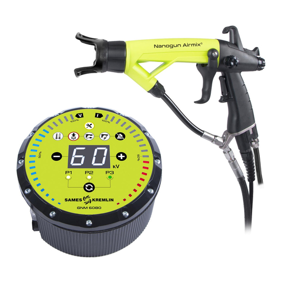
3. Description of spray gun and GNM 6080 control module ® The Nanogun Airmix O guns are for spraying water-soluble or water-dilutable water-based paint. Sprayed liquids must be non-flammable (defined in the draft standard pr EN 50059:2016 Annex C) and strongly conductive. The use of any other type of paint is excluded. -
Page 12: Gnm 6080 Control Module
“Default Acknowledgement” button (Rep. 3). Generator default: This default combines all internal generator defaults. If it is impos- sible to acknowledge this default, the problem would require a service call by the repairs department, please contact SAMES KREMLIN. Index revision : A 7118... - Page 13 Low-voltage connection default: The generator fails to detect or no longer detects the presence of the gun. After shutting off the power supply, verify the gun/genera- tor connection. High-voltage default: Defaults specific to gun operations related to the high voltage: •...
-
Page 14: Technical Characteristics
4. Technical characteristics 4.1. General characteristics of the guns Type of spray Flat Original head assembled Maximum incoming paint pressure 120 bar 200 bar Incoming compressed air pressure 6 bar ± 1 bar Min/max ambient temperature 0°C - 40°C Maximum water flow rate See table below Spray width at 25 cm See table below... -
Page 15: Flows
4.2. Flows Flat spray Flow rate (in cc/min) Width, in Gauge at 70 bar at 120 bar at 200 bar 03-05 03-07 04-05 04-07 04-09 04-11 04-13 06-09 06-11 06-13 06-15 09-09 09-11 09-13 09-15 12-11 1030 12-13 1030 12-15 1030 14-09 1230... -
Page 16: Characteristics Of The Gnm 6080
Note: The spraying air pressure must be set between 2 and 3 bars (4 for the K70 gauges); below this, the spraying becomes less precise and above the jet becomes more dynamic and the hol- low cone's benefits are reduced. 4.3. -
Page 17: Operations
5. Operations Pressing the trigger serves to delay the order to open the air valve, then activation of the high voltage, and lastly the paint nozzle needle. The high-voltage order may be inhibited by shifting the gun switch. ® The Nanogun Airmix O gun is equipped with a magnetic sensor that detects the trigger posi- tion. -
Page 18: Specific Tooling
6. Specific tooling Part Number Description Sales unit 900012843 Multipurpose wrench Part Number Description Sales unit H1GMIN017 White Vaseline (100 ml) Dielectric grease for the high-voltage cascade and H1GSYN037 nozzle needle channel (100 ml) Part Number Description Sales unit 900010160 Cartridge and air valve assembly tool Part Number Description... - Page 19 • Allen wrenches (3 - 6 mm) • Torque wrench 1 to 5 Nm (R.304DA Facom) (Ref. SAMES KREMLIN: 240000095) • Flat wrenches (5 - 5.5 - 11 - 15 - 17 - 18 - 21 - 24 - 27) •...
-
Page 20: Use Of The Multipurpose Wrench
6.1. Use of the multipurpose wrench 1 : Clamping of the head ring. 2 : Extraction of the head nozzle. Index revision : A 7118... -
Page 21: Installation
7. Installation WARNING : Before proceeding with any operation, please refer to the installation rules (see § 2.2 page With a piston pump for all versions Nanogun Airmix H O gun GNM 6080 control module Piston pump Insulating cabinet Short circuiter The paint intake must be installed within a ventilated zone. -
Page 22: Use
8. Use 8.1. Recommendations regarding the paint to be used In general, all the paints and varnishes used with conventional pneumatic guns are used nor- ® mally with the Nanogun Airmix O gun. the pigments contained in the paint should be less than 5 μm. -
Page 23: Spraying Rules
8.2. Spraying rules Regardless of the type of nozzle, the quality of spraying depends on both the supply pressure and the product viscosity: as viscosity increases, pressure must also rise, yet the final outcome is also influenced by the product’s dilution. A few key points: •... -
Page 24: Examples Of Poor Equipment Use
The non-exhaustive list below indicates the primary cases of poor paint spraying equipment use. WARNING : SAMES KREMLIN would like to recall therefore that it is essential to comply with the prescriptions listed below. It is prohibited to install the control module in an explosive atmosphere. -
Page 25: Maintenance
10. Maintenance 10.1. Summary table of preventive maintenance To be carried out when the maintenance indicator light on the GNM 6080 turns on. Minimum Part Subassembly Description replacement Number period O-ring - chemically inert J3STKL046 3 months Seat casing O-ring - chemically inert J3STKL075 3 months Flat seal... -
Page 26: Electro-Pneumatic Link
WARNING : Prior to any maintenance operation carried out on the gun, please refer to the health and safety instructions (see § 2 page - Turn off the the control module. - Verify that the air and paint circuits are no longer pressurised. - Dump the paint circuit. -
Page 27: Paint Hoses
10.3. Paint hoses It is not necessary to remove the electro-pneumatic coupling (see § 10.2 page 26) to complete these operations. • Step 1: Unscrew the locknut of the cable Step 1 gland using a 27 flat wrench, remove the cable gland from the bracket. -
Page 28: Spraying Head Assembly
10.4. Spraying head assembly Step 1 • Step 1: with the multipurpose wrench (Ref.: 900012843), unscrew the head ring. • Step 2: Extract the head nozzle using the mul- Step 2 tipurpose wrench. Do not use your fingers. If necessary, replace the head seal. For the reassembly step, proceed in the reverse order. -
Page 29: Replacement Of The Head Electrode
10.5. Replacement of the head electrode. Disassembly: • Step 1: Extract the conductive PTFE washer. Insert the blade of the screwdriver under the washer through one of the two slots at the rear of the head(do not use the housing where centering located). - Page 30 • Step 4: With the flat nose pliers, remove the small PTFE tube surrounding the electrode. Check that there are no residues in the pas- sage of the electrode. If necessary, manu- ally push a drill bit or a metal rod of 1 mm in the hole.
- Page 31 • Step 3: Clip the conductive PTFE washer. Replace it if necessary. It is recommended not to reuse the washer more than 3 to 4 times, and it must not be able to be removed without the aid of a tool. •...
-
Page 32: Barrel
10.6. Barrel • Step 1: Unscrew the seat casing using a 13- mm pipe wrench. Step 1 Then remove it. Should the O-rings and anti-extrusion rings located in front and back of the nozzle require replacement, remove them using a screwdriver, position the new rings and new seals in place while double checking their correct location and after coating them first... -
Page 33: Paint Nozzle Needle
• Step 3: Manually remove the adapter equipped with its O-ring and high-voltage Step 3 resistance by its spring and pulling on it. WARNING : Be careful not to damage the resistance during its extraction. 10.7. Paint nozzle needle • Step 1: Unscrew the knob at the back of the gun, and recover the spring. -
Page 34: Switch
10.8. Switch Step 1 • Step 1: With a 5.5-mm screwdriver, unscrew the washer head screw. Pull the switch lever upward. • Step 2: Replace the O-ring (see § 13.2 page 54). Insert the new switch into its housing. Coat the retaining screw with LOCTITE low strength thread lock and then clamp the screw so that the switch shows slight resist- ance. -
Page 35: Air Valve
10.10. Air valve • Step 1: Disassemble the paint nozzle needle (see § 10.7 page 33). • Step 2: Unscrew the air valve stop nut using an 18 flat wrench. Step 2 Point the gun barrel upwards and recover the spring and air valve. Should the parts not fall, tap in the palm of your hand or use the paint nozzle needle to withdraw the air valve. -
Page 36: Repairing Of The Air Valve
10.10.1. Repairing of the air valve Three levels of maintenance are possible: • Level 1: Standard level of maintenance since the air valve body is not subject to any fric- tion or wear. • Level 2: Corrective level, to be performed in case the valve body has deteriorated. •... -
Page 37: Fastening Hook
Level 3: If the magnet is broken or lost. • Replace the complete air valve (Ref.: 910015405) (see § 10.10 page 35). Before using the gun, inspect the high-voltage on and off switches. If the high-voltage is permanently activated, disassemble the handle and remove one of the washers that serve to adjust the reed sensor position;... -
Page 38: High-Voltage Cascade
10.12. High-voltage cascade • Step 1: Remove the trigger 34, and remove the paint nozzle needle. see § 10.9 page • Step 2: Unscrew the 4 screws using a 2-mm crosspoint screwdriver while holding the bar- rel on the handle. Note: Each time a screw is disassembled, replace the fibre washers as well (Ref.: Step 2... -
Page 39: Barrel
10.13. Barrel • Step 1: Remove the trigger 34, and the paint nozzle needle. see § 10.9 page • Step 2: Unscrew the four screws used to fasten the barrel onto the handle. • Step 3: Manually unscrew or by using a small flat pliers the three cascade connection wires, then carefully pull the contacts towards the back. -
Page 40: Handle
10.14. Handle • Step 1: Separate the barrel from the handle. • Step 2: Gun handle base Unscrew the air nipple using a 16 Allen wrench. Replace the seals every 12 months. Step 2 • Step 3: Unscrew the two screws (K35 x 14) with a 2 crosspoint screwdriver. -
Page 41: Electrical Diagrams
10.15. Electrical diagrams ® 10.15.1. GNM 6080 / Nanogun Airspray Airmix O connection cable ® Outlet for Nanogun Airmix Outlet on the GNM 6080 side Yellow Yellow Brown Brown White White Pink Pink Green Green Black Black 10.15.2. GNM 6080 trigger cord Outlet on the GNM 6080 side Pink Primary transformer UHT 3... -
Page 42: Cleaning
11. Cleaning Prior to any maintenance operation carried out on the gun, please refer to the health and safety instructions (see § 2 page 11.1. Cleaning of the product circuit • Unplug the GNM 6080 control module. • Install a bucket of solvent instead of a barrel of paint. •... -
Page 43: Hollow Cone Nozzle Cleaning
11.3. Hollow cone nozzle cleaning It is vital to clean the spraying head fully at the end of each shift or when use is interrupted, depending on the type of product between 5 and 30 minutes. Cleaning procedure: • Step 1: Disconnect the air and high voltage supplies. -
Page 44: Elimination Of Wastes
Reassembly: • Step 5: Remove the placebo injector. • Step 6: Coat the rear part (threading / seal) of the dielectric grease injector. • Step 7: Add more and/or put back the die- lectric grease on the HV contact. Coat the external thread of the barrel with dielectric grease. -
Page 45: Dismantling And Recycling
11.5. Dismantling and Recycling ® 11.5.1. Nanogun Airmix WARNING : All parts may be contaminated by paint and/or solvent residue. Before proceeding to dismantle the equipment, clean the gun and more specifi- cally the inside of the paint hoses with an appropriate cleaning product and dry them with compressed air. - Page 46 20*, 26*, 22, 31, 33 Stainless steel Plastic material containing fibre Plastic material, prefluorinated rubber 25*, 28 Aluminium 27, 29 Rubber Plastic material containing fibre, copper, stainless steel Fibre joint Polyamide not loaded Not represented Air hose: PU Product hose: PTFE - aramid - PU Not represented Fittings: zinc-plated steel or stainless steel Cable gland: plastic material containing fibres...
-
Page 47: Gnm 6080
11.5.2. GNM 6080 Rep. Description Material Keyboard / front side* Plastic material Fastening screws front side Steel Primary card support and front side Aluminium Electrical and electronic components, Primary card ROHS printed circuit Bottom sheet metal and fastening Steel screws Electrical and electronic components, Connector card ROHS printed circuit... -
Page 48: Common Malfunctions And Repairs
12. Common malfunctions and repairs Defaults Possible Causes Remedies Presence of air in the paint cir- Dump the paint circuit cuit Increase pressure at the pump Paint flow rate too slow or pressurised vessel. Uneven paint flow Verify the filters, then dump the Impurities in the circuit circuit. - Page 49 Defaults Possible Causes Remedies Evaporation of solvents too slow Use more lightweight solvents Running / dripping Slow the paint flow rate paint Speed of application too slow Decrease the electrostatic effect Decrease the paint flow rate Excessive paint flow rate Increase the air pressure Paint jet poorly dis- Nozzle too thick...
-
Page 50: Spare Parts
13. Spare parts ® 13.1. Nanogun Airmix O guns for water-based paint (LR) Index revision : A 7118... - Page 51 For the various options: see § 13.13 page Spare Sales Item Part Number Description parts level unit ® Nanogun Airmix O 120 bar JP with 910023074-075 09-091 nozzle and 7.5 m paint hose ® Nanogun Airmix O 120 bar JP with 910023074-150 09-091 nozzle and 15 m paint hose ®...
-
Page 52: The Nozzles As An Option
13.1.1. The nozzles as an option Part Number Description Quantity 130001597 Nozzle MX03.05 Option 130001563 Nozzle MX03.07 Option 130001564 Nozzle MX04.05 Option 130001565 Nozzle MX04.07 Option 130001566 Nozzle MX04.09 Option 130001414 Nozzle MX04.111 Option 130001415 Nozzle MX04.131 Option 130001416 Nozzle MX06.091 Option 130001417 Nozzle MX06.111... -
Page 53: Fitted Head Ring
13.1.2. Fitted head ring Sales Spare parts Item Part Number Description unit level (*) 910019358 Fitted head ring 900013829 Duckbill 900010164 PTFE flat seal 160000170 FEP/FKM seal Level 1: Standard preventive maintenance. Level 2: Corrective maintenance. Level 3: Exceptional maintenance. 13.1.3. -
Page 54: Nanogun Airmix ® H 2 O Gun
® 13.2. Nanogun Airmix O gun 25 26 Index revision : A 7118... - Page 55 Spare Sales Item Part Number Description parts level unit ® Nanogun Airmix O gun 910019359 Fitted seat casing (see § 13.3 page ® Fitted adapter Nanogun Airmix (see 910019360 § 13.4 page Fitted high-voltage contact (included in 910015934 Item 8) Chemically inert O-ring (included in Item J3STKL014 900014787...
- Page 56 900010009 LR gun base 910006118 Fitted air nipple J2FTCF018 Black FKM O-ring (included in Item 27) White chemically inert O-ring J3STKL018 (included in Item 27) 250000037 Base-handle fastening screw 910022663 Trigger / pin lock assembly 910018203 Fitted air valve (see § 13.6 page 900010237 Trigger 900014446...
-
Page 57: Equipped Seat Casing (Flat Spray Only)
13.3. Equipped seat casing (flat spray only) Spare Sales Item Part Number Description parts unit level (*) 910019359 Equipped seat casing J3STKL046 O-ring - chemically inert 900013368 Anti-extrusion ring 900012300 Anti-extrusion ring J3STKL075 O-ring - chemically inert 13.4. Equipped adapter (flat spray only) Spare Sales Item... -
Page 58: Equipped Barrel
13.5. Equipped barrel Spare Sales Item Part Number Description parts unit level (*) 910025082 Equipped barrel 910015881 Nozzle needle sealant cartridge 900012782 Anti-extrusion ring (included in Item 1) J3STKL005 O-ring - chemically inert (included in Item 1) J2FENV435 O-ring - FEP Viton J3STKL078 O-ring - chemically inert J3STKL019... -
Page 59: Equipped Air Valve And Air Valve Nut
Level 1: Standard preventive maintenance. Level 2: Corrective maintenance. Level 3: Exceptional maintenance. WARNING : Recover the magnet on the former air valve in order to retain the same trigger values. If the magnet is lost, contact SAMES KREMLIN. Index revision : A 7118... -
Page 60: Equipped Nozzle Needle
13.7. Equipped nozzle needle Sales Spare parts Item Part Number Description unit level (*) 910019508 Equipped nozzle needle X7CEHU003 H M3 U brass nut Level 1: Standard preventive maintenance. Level 2: Corrective maintenance. Level 3: Exceptional maintenance. 13.8. Electro-pneumatic coupling Connection GNM 6080 Spare... -
Page 61: Paint Hose
13.9. Paint hose 1a - 1b Sales Spare parts Item Part Number Description unit level (*) 910020165-075 Product hose LR PTFE 7.5m ∅ 5 910020165-150 Product hose LR PTFE 15m ∅ 5 Chemically inert O-ring (included in J3STKL028 Item 1) 900013398 Anti-extrusion ring (included in Item1) J2FTDF177... -
Page 62: Nanogun Airmix ® H 2 O Seal Kit
® 13.10. Nanogun Airmix O seal kit Part Number Title Location Quantity 910022694 ® Nanogun Airmix O seal kit Barrel, air valve, on/off J3STKL005 Chemically inert O-ring button J2FENV435 FEP/FKM O-ring Barrel J3STKL078 Chemically inert O-ring Barrel J3STKL019 Chemically inert O-ring Barrel 910015881 Nozzle needle sealant cartridge... -
Page 63: Hollow Cone Kit
13.11. Hollow cone kit (not available for North American market) Sales Spare parts Item Part Number Description unit level (*) 910025480-20 Hollow cone kit K20 910025480-30 Hollow cone kit K30 910025480-40 Hollow cone kit K40 910025480-50 Hollow cone kit K50 910025480-60 Hollow cone kit K60 910025480-70... -
Page 64: Equipped Hollow Cone Seat Casing
13.11.1. Equipped hollow cone seat casing Niveau Unité Pièces de Référence Description Qté rechange vente 910025478 Porte siège cône creux équipé 999469300 Pastille carbure de répartition 900012300 Bague anti-extrusion J3STKL075 Joint torique perfluoré Level 1: Standard preventive maintenance. Level 2: Corrective maintenance. Level 3: Exceptional maintenance. -
Page 65: Procedure For Changing From A Flat Spray To A Round Spray
13.11.2. Procedure for changing from a flat spray to a round spray WARNING : To carry out this operation, the gun must be disconnected from any supply (product / air / current). Remove the flat spray: 1 Loosen the cap nut (Ref.: 910019358). 2 Remove the cap (Ref.: 130001435), if the injector does not come away at the same time, remove it too 3 Loosen the seat casing (Ref.: 910019359) while pressing the trigger. -
Page 66: Gnm 6080 Control Module
13.12. GNM 6080 control module Sales Spare parts Item Part Number Description unit level (*) 910017193 GNM 6080 CE control module GNM 6080 CSA control module 910017192 (only USA and CANADA) 910005759 GNM 6080 fastening kit 842635 5-m mass cable, lug D: 6 Level 1: Standard preventive maintenance. -
Page 67: Appendices
13.14. Appendices 13.14.1. Hose protection casing This casing protects the hoses and cables, thereby guaranteeing flexibility and longevity. Description Part number Sales unit Rilsan hose protection duct with 30 collars 910021086 50-m roll 13.14.2. Gun protective cover Description Part Number Sales unit Protective cover 900011711...
Need help?
Do you have a question about the Nanogun Airmix H2O and is the answer not in the manual?
Questions and answers