Sign In
Upload
Download
Add to my manuals
Delete from my manuals
Share
URL of this page:
HTML Link:
Bookmark this page
Add
Manual will be automatically added to "My Manuals"
Print this page
×
Bookmark added
×
Added to my manuals
Manuals
Brands
AGCO Manuals
Farm Equipment
DynaFlex Series
Settings manual
AGCO DynaFlex Series Settings Manual
Header settings
Hide thumbs
1
2
Table Of Contents
3
4
5
6
7
8
9
10
11
12
13
14
15
16
17
18
19
20
21
22
23
24
25
26
27
28
29
30
31
32
33
34
35
36
37
38
39
40
41
42
43
44
45
46
47
48
49
50
51
52
53
54
55
56
57
58
59
60
61
62
63
64
page
of
64
Go
/
64
Bookmarks
Advertisement
Quick Links
Download this manual
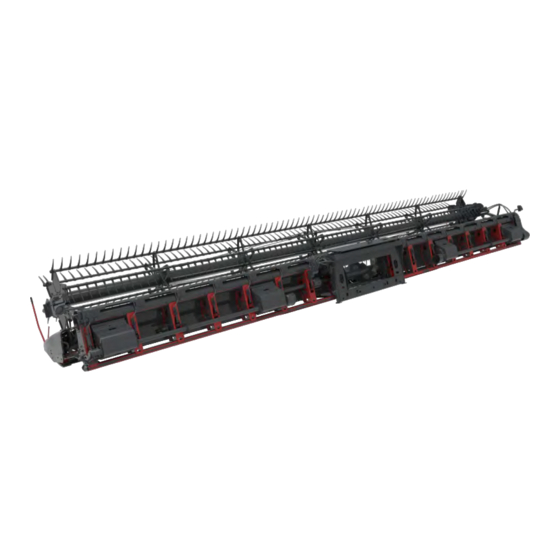
HeaderSettings Guide
DynaFlex& Command Series
Previous
Page
Next
Page
1
2
3
4
5
Advertisement
Need help?
Do you have a question about the DynaFlex Series and is the answer not in the manual?
Ask a question
Questions and answers
Related Manuals for AGCO DynaFlex Series
Farm Equipment AGCO Glencoe DR8500 Series Operator's Manual
Disc ripper (52 pages)
Farm Equipment AGCO Glencoe DR8700 Operator's Manual
Fold series disc ripper (46 pages)
Farm Equipment AGCO Gleaner DynaFlex 9250 Service Manual
Draper header (41 pages)
Farm Equipment AGCO LELY ATTIS PT 130 Operator's Manual
Bale wrapper (98 pages)
Farm Equipment AGCO Glencoe ULTRAMULCHER UM43 21’ Operator's Manual
(53 pages)
Farm Equipment AGCO Glencoe CC4450 Operator's Manual
Combination chisel plow (37 pages)
Farm Equipment AGCO FENDT 5250L Workshop Manual
(41 pages)
Farm Equipment AGCO Glencoe SS7400 Assembly Instructions Manual
Primary tillage (51 pages)
Farm Equipment AGCO GLEANER 3000 Service Manual
Corn header (31 pages)
Farm Equipment AGCO Challenger Terra Gator 3244 Service Manual
(41 pages)
Farm Equipment AGCO RoGator 900 Installation Manual
Hawkeye nozzle control system installation (46 pages)
Farm Equipment AGCO Massey Ferguson 9195 Service Manual
Rotary disc header (41 pages)
Farm Equipment AGCO FENDT 5220E Workshop Manual
(41 pages)
Farm Equipment AGCO Glencoe CM41 Operator's Manual
Cultimulcher 18' non-folding models (44 pages)
Farm Equipment AGCO Gleaner S67 Operator's Manual
(40 pages)
Farm Equipment AGCO Hawkeye RoGator RG900 Installation Manual
(50 pages)
This manual is also suitable for:
Command series
3300 command
Print
Rename the bookmark
Delete bookmark?
Delete from my manuals?
Login
Sign In
OR
Sign in with Facebook
Sign in with Google
Upload manual
Upload from disk
Upload from URL


Need help?
Do you have a question about the DynaFlex Series and is the answer not in the manual?
Questions and answers